How to Use converter: Examples, Pinouts, and Specs
Introduction
A converter is an electronic device designed to transform electrical energy from one form to another. This includes converting alternating current (AC) to direct current (DC), changing voltage levels, or even modifying frequency. Converters are essential in modern electronics, enabling compatibility between different power sources and devices.
Common applications of converters include:
- Power supplies for electronic devices (e.g., AC-DC adapters for laptops and phones)
- Voltage regulation in renewable energy systems (e.g., solar inverters)
- Motor control in industrial applications
- Battery charging systems
- DC-DC converters for automotive and aerospace systems
Explore Projects Built with converter


Explore Projects Built with converter
Technical Specifications
The technical specifications of a converter can vary depending on its type and application. Below are general specifications for a typical AC-DC converter:
General Specifications
| Parameter | Value |
|---|---|
| Input Voltage Range | 100-240V AC |
| Output Voltage Range | 5V DC, 12V DC, 24V DC (varies) |
| Output Current | 1A to 10A (depending on model) |
| Efficiency | 85% to 95% |
| Operating Temperature | -20°C to 70°C |
| Protection Features | Overvoltage, Overcurrent, |
| Short Circuit Protection |
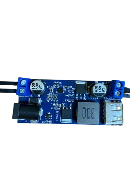
Pin Configuration (Example: DC-DC Converter Module)
| Pin Number | Pin Name | Description |
|---|---|---|
| 1 | VIN | Input voltage (e.g., 12V DC) |
| 2 | GND | Ground connection |
| 3 | VOUT | Output voltage (e.g., 5V DC) |
| 4 | ADJ (optional) | Voltage adjustment pin (if available) |
Usage Instructions
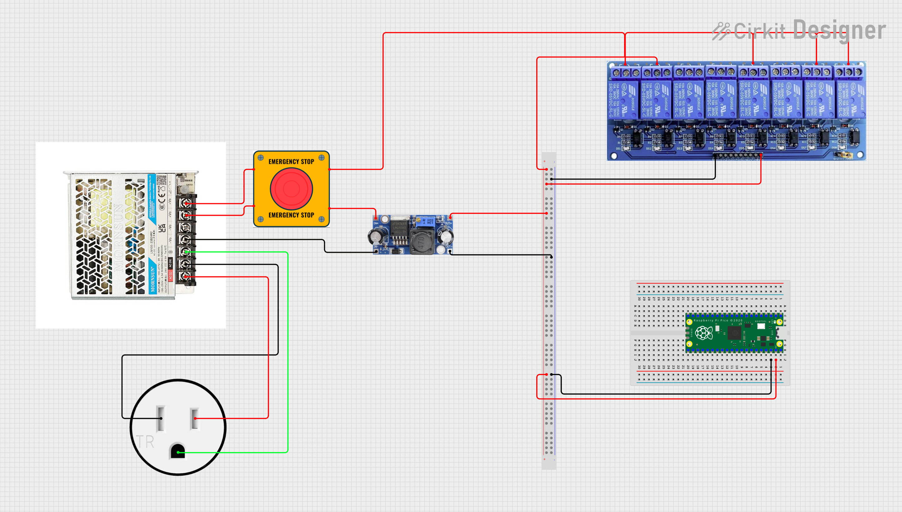
How to Use the Converter in a Circuit
- Identify Input and Output Requirements: Determine the input voltage and current your converter requires, as well as the desired output voltage and current for your application.
- Connect Input Power: Attach the input voltage source to the VIN and GND pins of the converter. Ensure the input voltage is within the specified range.
- Connect the Load: Connect the device or circuit you want to power to the VOUT and GND pins of the converter.
- Adjust Output Voltage (if applicable): If the converter has an adjustable output, use the ADJ pin or onboard potentiometer to set the desired output voltage.
- Test the Circuit: Power on the input source and measure the output voltage with a multimeter to confirm proper operation.
Important Considerations and Best Practices
- Heat Dissipation: Converters can generate heat during operation. Ensure proper ventilation or use a heatsink if necessary.
- Input Voltage Range: Always verify that the input voltage is within the converter's specified range to avoid damage.
- Load Compatibility: Ensure the connected load does not exceed the converter's maximum output current.
- Polarity: Double-check the polarity of connections to avoid damaging the converter or connected devices.
Example: Using a DC-DC Converter with Arduino UNO
Below is an example of using a DC-DC converter to power an Arduino UNO with a 12V input source:
// Example: Powering Arduino UNO with a DC-DC Converter
// Connect the converter's VOUT to the Arduino's VIN pin
// Ensure the converter's output is set to 7-12V DC

void setup() {
  // Initialize serial communication for debugging
  Serial.begin(9600);
  Serial.println("Arduino powered via DC-DC Converter");
}

void loop() {
  // Main loop does nothing in this example
  delay(1000);
}
Troubleshooting and FAQs
Common Issues and Solutions
No Output Voltage
- Cause: Input voltage is not connected or is outside the specified range.
- Solution: Verify the input voltage and connections.
Overheating
- Cause: Excessive load or poor ventilation.
- Solution: Reduce the load or improve airflow around the converter.
Output Voltage Fluctuations
- Cause: Insufficient input power or unstable input source.
- Solution: Ensure the input source is stable and capable of supplying sufficient current.
Device Not Powering On
- Cause: Incorrect polarity or loose connections.
- Solution: Double-check all connections and ensure correct polarity.
FAQs
Q: Can I use a converter to power sensitive electronics?
A: Yes, but ensure the converter provides a stable output voltage and includes protection features like overvoltage and short circuit protection.
Q: How do I adjust the output voltage of a converter?
A: If the converter has an adjustable output, use the onboard potentiometer or ADJ pin to fine-tune the voltage. Refer to the datasheet for specific instructions.
Q: Can I use a converter with a battery?
A: Yes, converters are commonly used with batteries to step up or step down voltage levels. Ensure the converter's input range matches the battery voltage.
Q: What happens if I exceed the maximum output current?
A: Exceeding the maximum output current can cause the converter to overheat, shut down, or become damaged. Always stay within the specified limits.