
How to Use COPERNICUS: Examples, Pinouts, and Specs
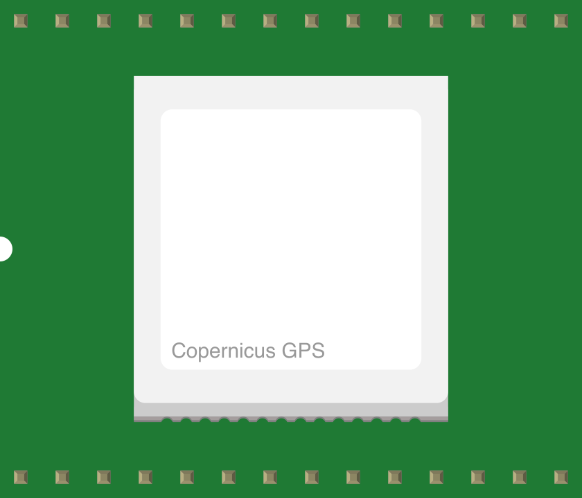
 Design with COPERNICUS in Cirkit Designer
Introduction
The COPERNICUS II module, manufactured by Trimble, is a high-performance satellite navigation system designed to provide precise positioning and timing information globally. As part of the European Global Navigation Satellite System (GNSS), it enhances the capabilities of existing systems like GPS, offering improved accuracy, reliability, and coverage. The module is compact, power-efficient, and ideal for integration into a wide range of applications.
Explore Projects Built with COPERNICUS
 Open Project in Cirkit Designer
 Open Project in Cirkit Designer
 Open Project in Cirkit Designer
 Open Project in Cirkit Designer
Explore Projects Built with COPERNICUS
Open Project in Cirkit DesignerOpen Project in Cirkit DesignerOpen Project in Cirkit DesignerOpen Project in Cirkit DesignerCommon Applications and Use Cases
- Geolocation Services: Used in mapping, surveying, and navigation systems.
- Timing and Synchronization: Provides precise timing for telecommunications, power grids, and financial systems.
- Autonomous Systems: Supports drones, autonomous vehicles, and robotics.
- IoT Devices: Enables location-based services in smart devices and wearables.
Technical Specifications
Key Technical Details
| Parameter | Specification |
|---|---|
| Manufacturer | Trimble |
| Model | Copernicus II |
| GNSS Support | GPS, Galileo, GLONASS, SBAS |
| Frequency Bands | L1 (1575.42 MHz) |
| Position Accuracy | < 2.5 meters (CEP) |
| Timing Accuracy | < 20 nanoseconds |
| Acquisition Time | Cold Start: < 35 seconds |
| Hot Start: < 1 second | |
| Supply Voltage | 3.0V to 3.6V |
| Power Consumption | < 100 mW (typical) |
| Operating Temperature | -40°C to +85°C |
| Dimensions | 19 mm x 19 mm x 2.5 mm |
| Interface | UART, SPI, I2C |
Pin Configuration and Descriptions
| Pin Number | Pin Name | Description |
|---|---|---|
| 1 | VCC | Power supply input (3.0V to 3.6V) |
| 2 | GND | Ground connection |
| 3 | TXD | UART Transmit Data |
| 4 | RXD | UART Receive Data |
| 5 | PPS | Pulse Per Second output for timing |
| 6 | RESET | Active-low reset input |
| 7 | SPI_CLK | SPI Clock |
| 8 | SPI_MOSI | SPI Master Out Slave In |
| 9 | SPI_MISO | SPI Master In Slave Out |
| 10 | I2C_SCL | I2C Clock |
| 11 | I2C_SDA | I2C Data |
| 12 | ANT_IN | Antenna input |
Usage Instructions
How to Use the Component in a Circuit
- Power Supply: Connect the VCC pin to a regulated 3.3V power source and GND to the ground.
- Antenna Connection: Attach an active GNSS antenna to the ANT_IN pin for optimal signal reception.
- Data Communication: Use the UART, SPI, or I2C interface to communicate with a microcontroller or host system.
- Timing Signal: Utilize the PPS pin for precise timing synchronization in your application.
- Reset: Connect the RESET pin to a microcontroller GPIO or a manual push-button for resetting the module.
Important Considerations and Best Practices
- Antenna Placement: Ensure the antenna has a clear view of the sky for optimal satellite reception.
- Power Filtering: Use decoupling capacitors near the VCC pin to minimize noise and ensure stable operation.
- Signal Integrity: Keep data lines short and use proper shielding to reduce interference.
- Firmware Updates: Periodically check for firmware updates from Trimble to ensure compatibility and performance.
Example: Connecting to an Arduino UNO
Below is an example of interfacing the COPERNICUS II module with an Arduino UNO using UART communication.
#include <SoftwareSerial.h>

// Define RX and TX pins for communication with the Copernicus II module
SoftwareSerial copernicusSerial(10, 11); // RX = Pin 10, TX = Pin 11

void setup() {
  Serial.begin(9600); // Initialize Serial Monitor at 9600 baud
  copernicusSerial.begin(9600); // Initialize Copernicus II UART at 9600 baud

  Serial.println("Initializing Copernicus II Module...");
}

void loop() {
  // Check if data is available from the Copernicus II module
  if (copernicusSerial.available()) {
    String gpsData = copernicusSerial.readStringUntil('\n'); // Read GPS data line
    Serial.println("GPS Data: " + gpsData); // Print GPS data to Serial Monitor
  }

  // Send commands to the module if needed
  // Example: copernicusSerial.println("$PMTK..."); // Replace with actual command
}
Troubleshooting and FAQs
Common Issues and Solutions
No Satellite Fix:
- Cause: Poor antenna placement or obstruction.
- Solution: Place the antenna in an open area with a clear view of the sky.
No Data Output:
- Cause: Incorrect baud rate or wiring.
- Solution: Verify the UART baud rate (default: 9600) and check connections.
High Power Consumption:
- Cause: Faulty power supply or excessive noise.
- Solution: Use a stable, low-noise power source and add decoupling capacitors.
Timing Signal Unstable:
- Cause: Interference or improper grounding.
- Solution: Ensure proper grounding and minimize interference near the PPS line.
FAQs
Q: Can the module operate indoors?
- A: The module may work indoors near windows, but performance is significantly reduced. Use an external antenna for better results.
Q: What is the default communication protocol?
- A: The default protocol is UART at 9600 baud, but SPI and I2C are also supported.
Q: Is the module compatible with GPS-only systems?
- A: Yes, the module supports GPS in addition to Galileo, GLONASS, and SBAS.
Q: How do I update the firmware?
- A: Firmware updates can be downloaded from Trimble's website and uploaded via the UART or SPI interface.
This documentation provides a comprehensive guide to using the COPERNICUS II module effectively in your projects.