How to Use DC Breaker: Examples, Pinouts, and Specs
Introduction
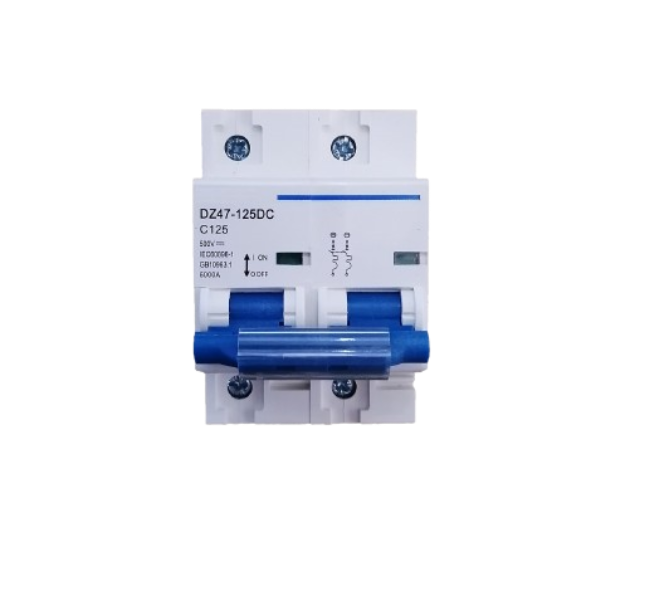
A DC breaker is a protective device designed to interrupt the flow of direct current (DC) in an electrical circuit. Its primary purpose is to safeguard electrical systems by preventing damage caused by overloads, short circuits, or other electrical faults. Unlike AC breakers, DC breakers are specifically engineered to handle the unique challenges of breaking direct current, such as the absence of zero-crossing points in the waveform.
Explore Projects Built with DC Breaker
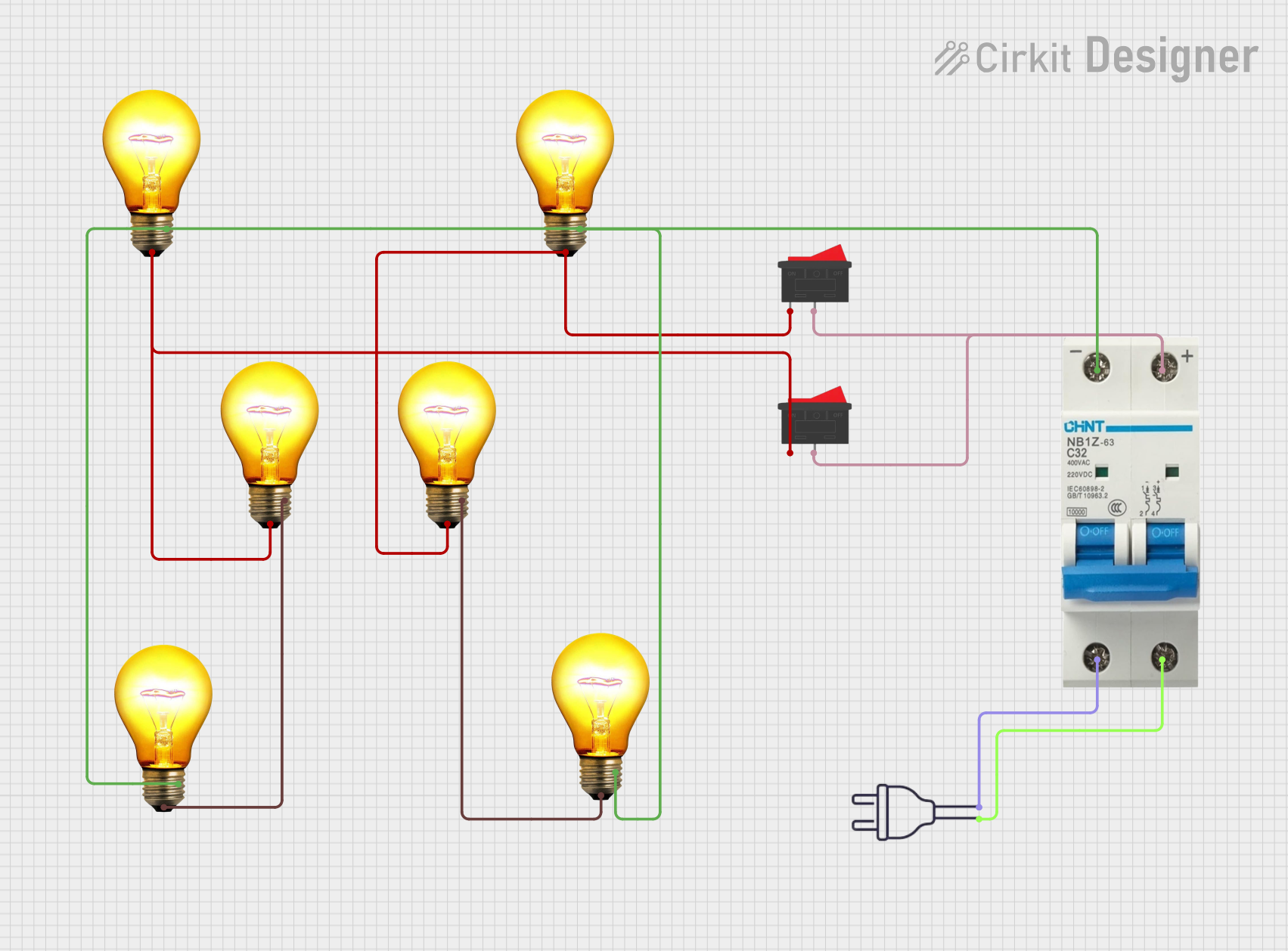
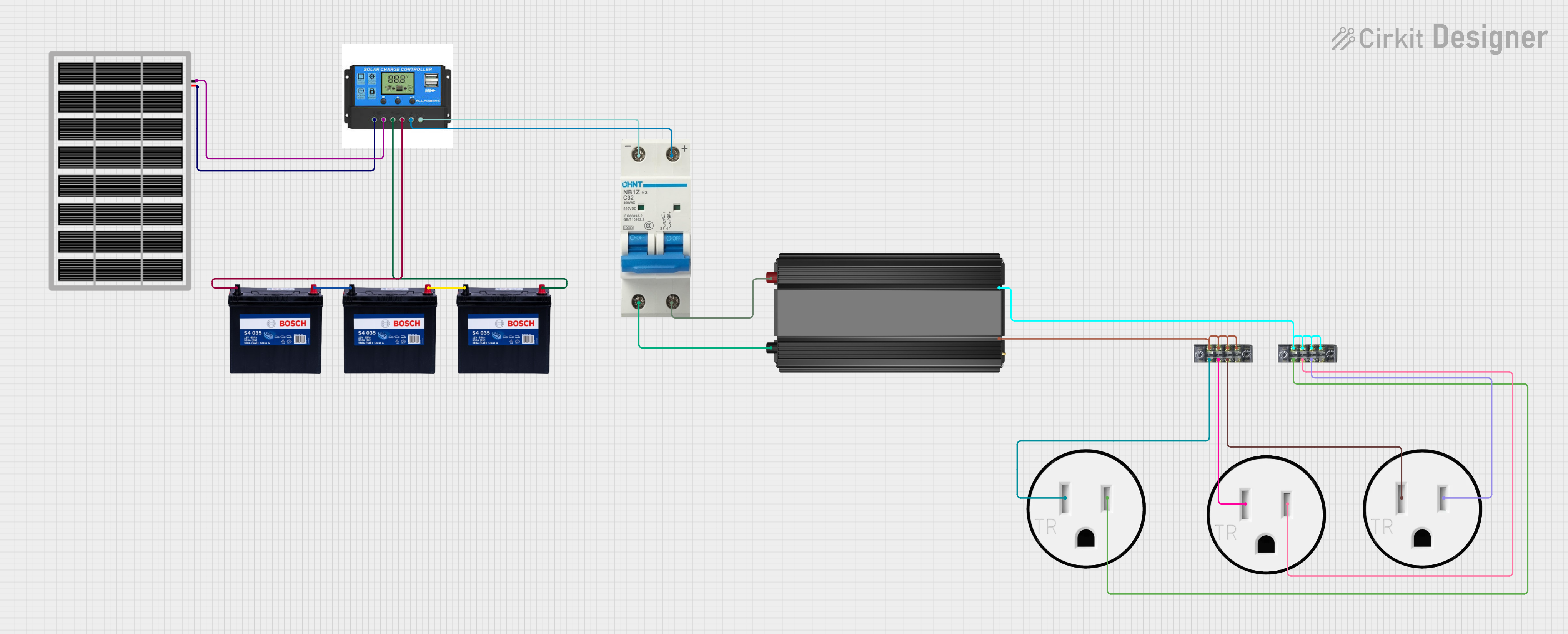

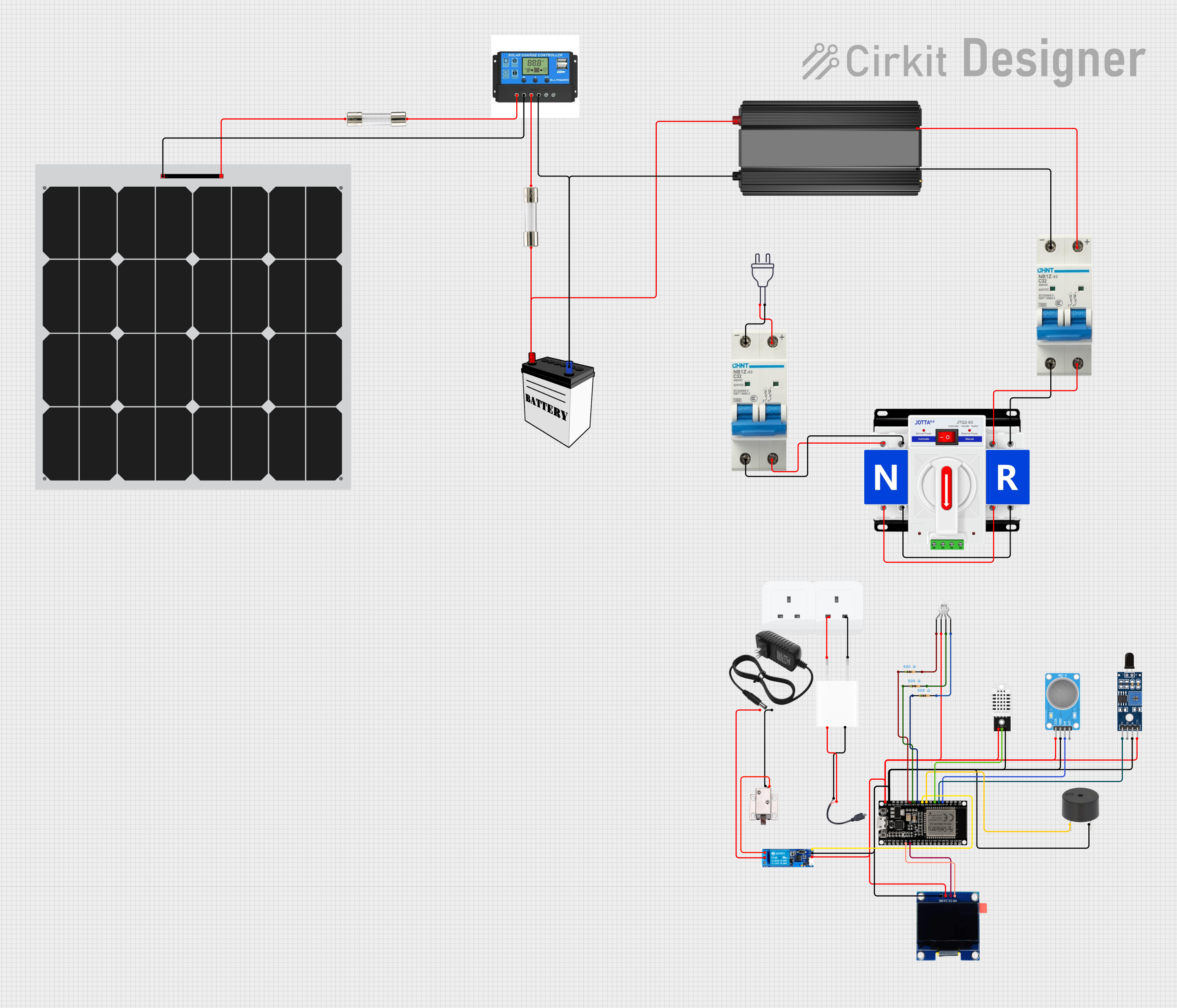
Explore Projects Built with DC Breaker
Common Applications and Use Cases
- Solar power systems to protect photovoltaic (PV) arrays and inverters.
- Electric vehicle (EV) charging stations for circuit protection.
- Battery energy storage systems (BESS) to prevent overcurrent damage.
- Industrial DC motor control circuits.
- Telecommunications equipment and data centers.
Technical Specifications
Below are the key technical details for a typical DC breaker. Always refer to the datasheet of the specific model you are using for precise specifications.
General Specifications
- Rated Voltage: 12V to 1000V DC (varies by model)
- Rated Current: 1A to 1000A (varies by model)
- Breaking Capacity: Up to 50 kA (depending on the model)
- Trip Mechanism: Thermal-magnetic or electronic
- Poles: Single-pole, double-pole, or multi-pole configurations
- Operating Temperature: -25°C to +70°C
- Mounting: DIN rail or panel-mounted
Pin Configuration and Descriptions
DC breakers typically have input and output terminals for connecting to the circuit. Below is a table describing the terminals:
| Terminal | Description |
|---|---|
| Input (+) | Positive terminal for incoming DC power. |
| Input (-) | Negative terminal for incoming DC power. |
| Output (+) | Positive terminal for outgoing DC power. |
| Output (-) | Negative terminal for outgoing DC power. |
Some advanced DC breakers may include auxiliary terminals for monitoring or remote control. Refer to the specific model's manual for details.
Usage Instructions
How to Use the Component in a Circuit
- Determine the Ratings: Select a DC breaker with a voltage and current rating suitable for your circuit. Ensure the breaking capacity exceeds the maximum fault current of your system.
- Connect the Input Terminals: Connect the positive and negative input terminals of the breaker to the DC power source.
- Connect the Output Terminals: Connect the positive and negative output terminals to the load or downstream circuit.
- Secure the Breaker: Mount the breaker on a DIN rail or panel as per the installation requirements.
- Test the Circuit: After installation, test the breaker by simulating an overload or short circuit to ensure proper operation.
Important Considerations and Best Practices
- Polarity: Ensure correct polarity when connecting the breaker, as DC breakers are polarity-sensitive.
- Derating: Consider derating the breaker if operating in high-temperature environments.
- Arc Suppression: Use breakers with arc-extinguishing chambers for high-voltage applications to prevent damage during tripping.
- Maintenance: Periodically inspect the breaker for signs of wear, corrosion, or damage.
Example: Using a DC Breaker in a Solar System
In a solar power system, a DC breaker can be installed between the solar panels and the charge controller to protect against overcurrent. Below is an example of how to connect the breaker:
Solar Panel (+) ----> DC Breaker Input (+)
Solar Panel (-) ----> DC Breaker Input (-)
DC Breaker Output (+) ----> Charge Controller (+)
DC Breaker Output (-) ----> Charge Controller (-)
Troubleshooting and FAQs
Common Issues Users Might Face
Breaker Does Not Trip During Overload:
- Cause: Incorrect breaker rating or faulty trip mechanism.
- Solution: Verify the breaker’s current rating matches the circuit requirements. Replace the breaker if defective.
Breaker Trips Frequently:
- Cause: Overloaded circuit or short circuit.
- Solution: Check the circuit for excessive load or wiring faults. Reduce the load or repair the fault.
Breaker Fails to Reset:
- Cause: Internal damage or persistent fault in the circuit.
- Solution: Inspect the breaker for damage. Ensure the circuit is fault-free before resetting.
Arcing During Tripping:
- Cause: High voltage without proper arc suppression.
- Solution: Use a breaker with an arc-extinguishing chamber for high-voltage applications.
FAQs
Q: Can I use an AC breaker in a DC circuit?
A: No, AC breakers are not designed to handle the continuous current flow and arcing characteristics of DC circuits. Always use a DC-rated breaker.Q: How do I select the correct DC breaker for my application?
A: Determine the maximum voltage, current, and fault current of your circuit. Choose a breaker with ratings that meet or exceed these values.Q: Can a DC breaker be used for bidirectional current flow?
A: Some DC breakers are designed for bidirectional use, but most are polarity-sensitive. Check the specifications of your breaker.Q: How often should I inspect my DC breaker?
A: Perform visual inspections every 6-12 months and test the breaker annually to ensure proper functionality.