How to Use Gledopto GL-C-309WL: Examples, Pinouts, and Specs
Introduction
The Gledopto GL-C-309WL is a versatile smart LED controller designed to manage RGB and white LED lights. It supports both Wi-Fi and Zigbee protocols, making it compatible with a wide range of smart home ecosystems, including Amazon Alexa, Google Assistant, and Zigbee hubs like Philips Hue. This controller allows users to remotely control lighting, adjust brightness, and change colors, enabling seamless automation and customization of lighting environments.
Explore Projects Built with Gledopto GL-C-309WL

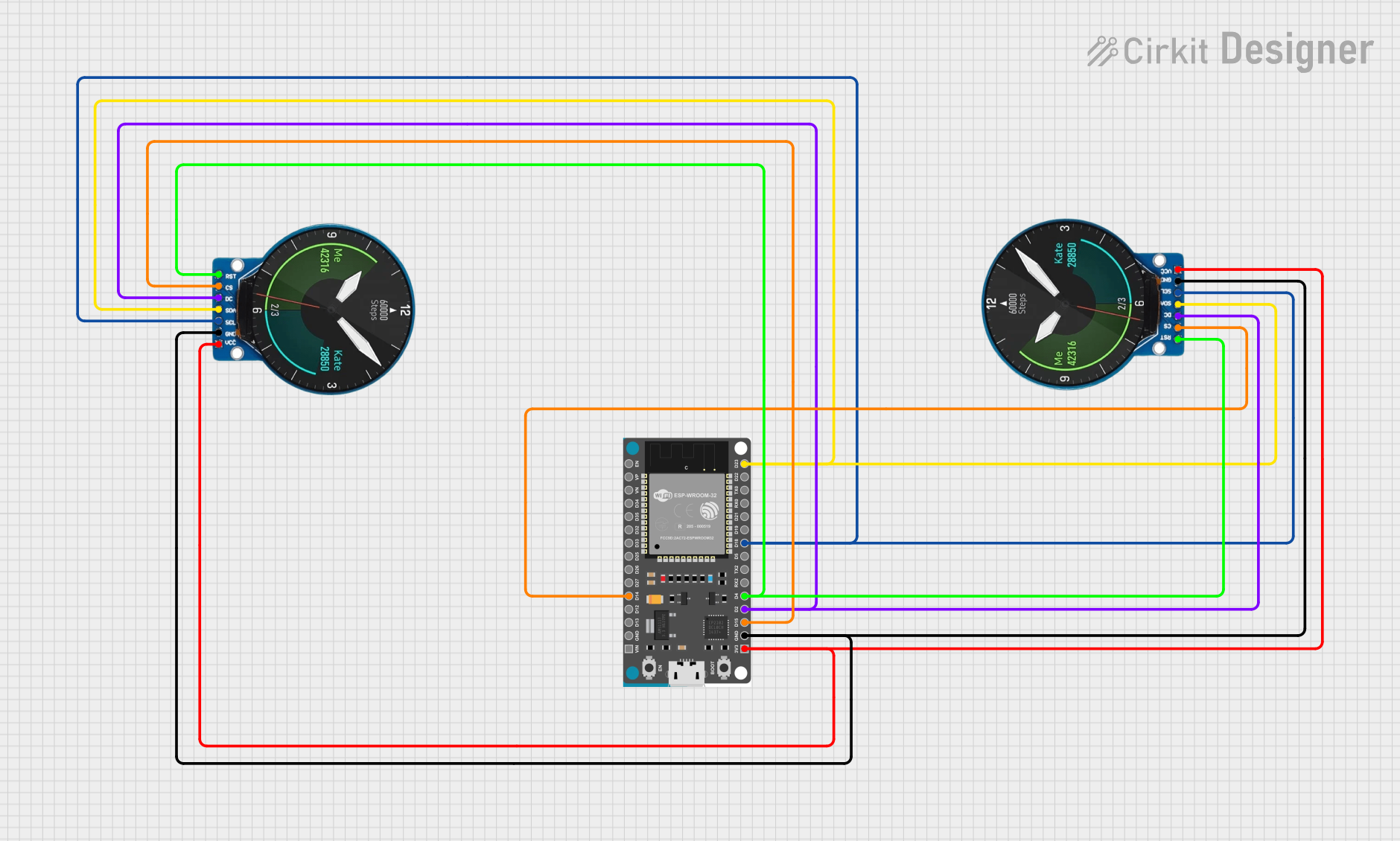
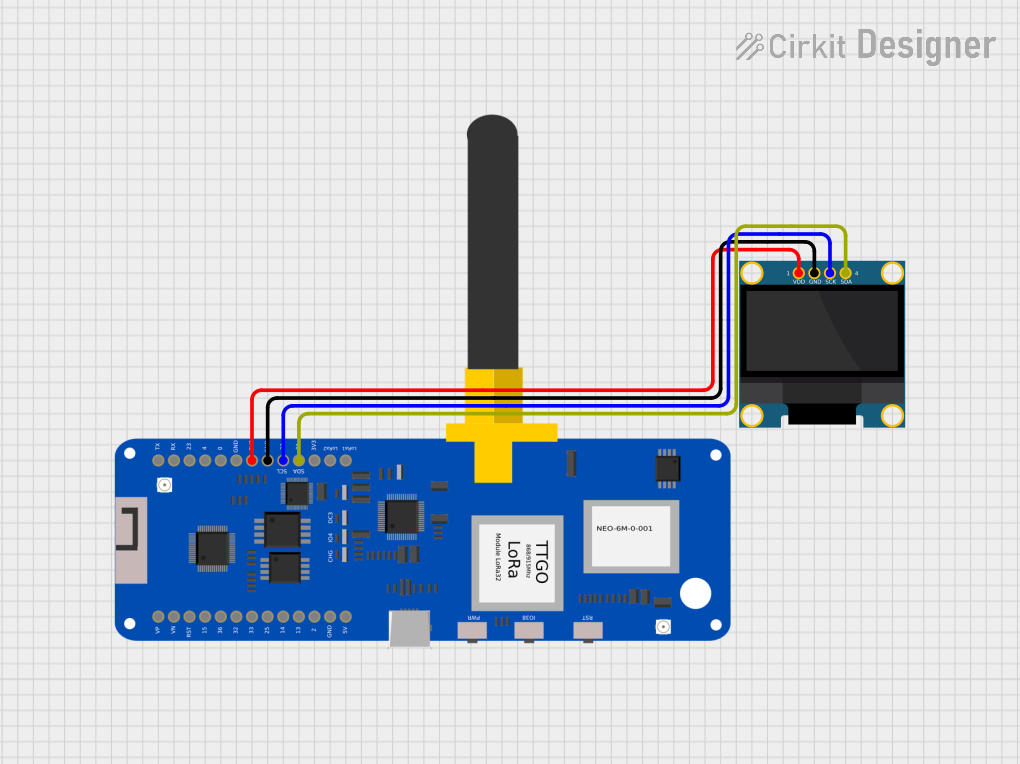
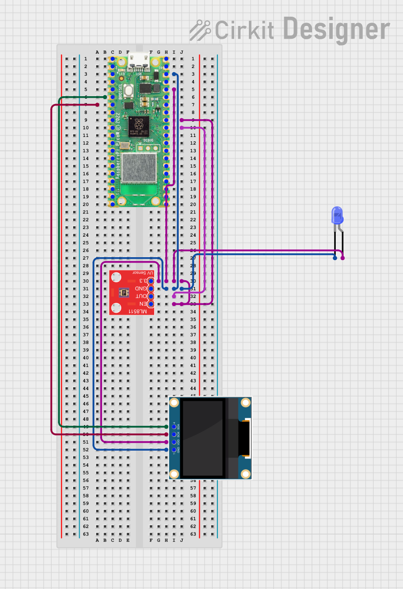
Explore Projects Built with Gledopto GL-C-309WL
Common Applications and Use Cases
- Smart home lighting systems
- Ambient lighting for residential and commercial spaces
- Dynamic color-changing effects for events and decorations
- Integration with voice assistants for hands-free control
- Automated lighting schedules and scenes
Technical Specifications
Key Technical Details
| Parameter | Specification |
|---|---|
| Model Number | GL-C-309WL |
| Input Voltage | DC 12V-24V |
| Output Current | Max 6A per channel (RGBW) |
| Total Output Power | 144W (12V) / 288W (24V) |
| Communication Protocol | Wi-Fi (2.4 GHz) / Zigbee |
| Supported LED Types | RGB, RGBW |
| Control Methods | Mobile App, Voice Assistants, Zigbee |
| Dimensions | 85mm x 45mm x 22mm |
| Operating Temperature | -20°C to 60°C |
Pin Configuration and Descriptions
The GL-C-309WL has a set of input and output terminals for power and LED connections. Below is the pin configuration:
Input Terminals
| Pin Name | Description |
|---|---|
| V+ | Positive DC input (12V-24V) |
| V- | Negative DC input (Ground) |
Output Terminals
| Pin Name | Description |
|---|---|
| R | Red LED channel output |
| G | Green LED channel output |
| B | Blue LED channel output |
| W | White LED channel output |
| V+ | Common positive for LED connections |
Usage Instructions
How to Use the Component in a Circuit
- Power Connection: Connect a DC power supply (12V or 24V) to the input terminals (V+ and V-). Ensure the power supply matches the voltage requirements of your LED strip.
- LED Connection: Connect the RGBW LED strip to the output terminals (R, G, B, W, and V+). Ensure proper polarity and match the LED type (RGB or RGBW).
- Communication Setup:
- For Wi-Fi: Use the Gledopto app or a compatible smart home app to connect the controller to your 2.4 GHz Wi-Fi network.
- For Zigbee: Pair the controller with a Zigbee hub (e.g., Philips Hue Bridge) following the hub's pairing instructions.
- Control: Use the app, voice assistant, or Zigbee hub to control the lights. You can adjust brightness, change colors, and create lighting scenes.
Important Considerations and Best Practices
- Voltage Compatibility: Ensure the power supply voltage matches the LED strip's requirements (12V or 24V).
- Current Limitations: Do not exceed the maximum current rating of 6A per channel to avoid damage.
- Heat Management: Install the controller in a well-ventilated area to prevent overheating.
- Wi-Fi Network: Use a 2.4 GHz Wi-Fi network for optimal performance. The controller does not support 5 GHz networks.
- Zigbee Pairing: Reset the controller (if needed) by powering it off and on 5 times in quick succession to enter pairing mode.
Example Code for Arduino UNO (Zigbee Integration)
If you are using the GL-C-309WL with an Arduino UNO and a Zigbee module (e.g., XBee), you can send Zigbee commands to control the lights. Below is an example code snippet:
#include <SoftwareSerial.h>

// Define RX and TX pins for Zigbee communication
SoftwareSerial zigbeeSerial(2, 3); // RX = pin 2, TX = pin 3

void setup() {
  // Initialize serial communication
  Serial.begin(9600);
  zigbeeSerial.begin(9600);

  // Send a sample Zigbee command to turn on the lights
  // Replace "0x00" with the appropriate Zigbee address of the controller
  byte command[] = {0x00, 0x11, 0x22, 0x33, 0x44};
  // Example command to set RGBW values (adjust as needed)
  zigbeeSerial.write(command, sizeof(command));

  Serial.println("Zigbee command sent to GL-C-309WL.");
}

void loop() {
  // Add your logic to send additional commands or process responses
}
Note: Replace the command array with the appropriate Zigbee command for your application. Consult the Zigbee hub or controller documentation for specific command formats.
Troubleshooting and FAQs
Common Issues and Solutions
LEDs Not Lighting Up:
- Check the power supply voltage and ensure it matches the LED strip's requirements.
- Verify all connections, especially the polarity of the input and output terminals.
- Ensure the controller is powered on and properly paired with the app or Zigbee hub.
Wi-Fi Connection Fails:
- Ensure the Wi-Fi network is 2.4 GHz (not 5 GHz).
- Move the controller closer to the router during the setup process.
- Reset the controller and try pairing again.
Zigbee Pairing Issues:
- Ensure the Zigbee hub is in pairing mode.
- Reset the controller by powering it off and on 5 times quickly to enter pairing mode.
- Check for interference from other Zigbee devices.
Overheating:
- Ensure the controller is installed in a well-ventilated area.
- Avoid exceeding the maximum current rating of 6A per channel.
FAQs
Can I use this controller with a 5 GHz Wi-Fi network? No, the GL-C-309WL only supports 2.4 GHz Wi-Fi networks.
What is the maximum length of LED strips I can connect? The maximum length depends on the power requirements of the LED strip. Ensure the total current does not exceed 6A per channel.
Can I control the lights without a Zigbee hub? Yes, you can use the Wi-Fi functionality and control the lights via the Gledopto app or a compatible smart home app.
How do I reset the controller? Power off and on the controller 5 times in quick succession to reset it and enter pairing mode.
This concludes the documentation for the Gledopto GL-C-309WL. For further assistance, refer to the manufacturer's user manual or contact Gledopto support.