Cirkit Designer Logo
Cirkit Designer
Your all-in-one circuit design IDE
Home / 
Component Documentation

How to Use GPS Matek M10-5883: Examples, Pinouts, and Specs

Image of GPS Matek M10-5883
Cirkit Designer LogoDesign with GPS Matek M10-5883 in Cirkit Designer

Introduction

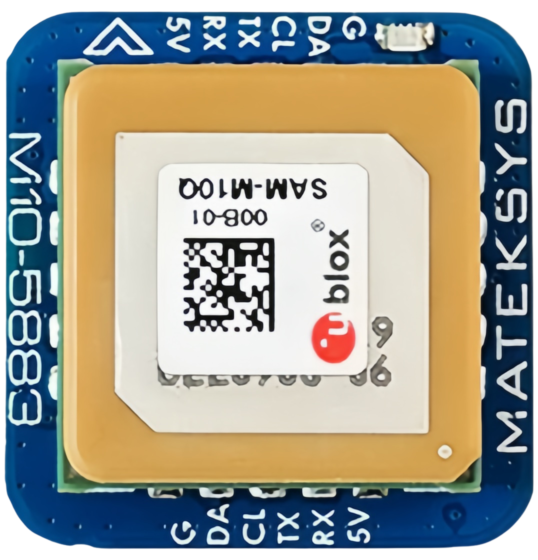
The GPS Matek M10-5883 is a high-performance GPS module designed for applications requiring precise positioning and navigation. It features a 10Hz update rate, a built-in antenna, and support for multiple GNSS (Global Navigation Satellite Systems), including GPS, GLONASS, Galileo, and BeiDou. This module is particularly well-suited for drones, robotics, and other systems where accurate and reliable location data is critical.

Explore Projects Built with GPS Matek M10-5883

Use Cirkit Designer to design, explore, and prototype these projects online. Some projects support real-time simulation. Click "Open Project" to start designing instantly!
ESP32-Based GPS Tracker with OLED Display and Firebase Integration
Image of ecs: A project utilizing GPS Matek M10-5883 in a practical application
This circuit is a GPS tracking system that uses an ESP32 microcontroller to read location data from a NEO-6M GPS module and display information on a 0.96" OLED screen. The system is powered by a 2000mAh battery with a lithium-ion charger, and it uploads the GPS data to Firebase via WiFi. Additional components include an MPU6050 accelerometer/gyroscope for motion sensing and a buzzer for alerts.
Cirkit Designer LogoOpen Project in Cirkit Designer
Solar-Powered GPS Tracker with ESP32 and TFT Display
Image of Project Hajj: A project utilizing GPS Matek M10-5883 in a practical application
This circuit is a solar-powered GPS tracking system with a display. It uses multiple solar panels to charge two 2000mAh batteries via a LiPo battery charger module, which powers an ESP32 microcontroller, a GPS NEO 6M module, and an ILI9341 TFT display. The ESP32 reads GPS coordinates and displays them on the TFT screen, updating every 5 seconds.
Cirkit Designer LogoOpen Project in Cirkit Designer
ESP8266 Controlled Robotics Platform with GPS, IR, and GSM Features
Image of IOT based Trash Collecting Vessel: A project utilizing GPS Matek M10-5883 in a practical application
This is a microcontroller-based control system designed for a mobile robotic platform with environmental sensing, location tracking, and GSM communication capabilities. It includes motor control for actuation, various sensors for data acquisition, and a battery for power supply.
Cirkit Designer LogoOpen Project in Cirkit Designer
Satellite-Based Timing and Navigation System with SDR and Atomic Clock Synchronization
Image of GPS 시스템 측정 구성도_Confirm: A project utilizing GPS Matek M10-5883 in a practical application
This circuit appears to be a complex system involving power supply management, GPS and timing synchronization, and data communication. It includes a SI-TEX G1 Satellite Compass for GPS data, an XHTF1021 Atomic Rubidium Clock for precise timing, and Ettus USRP B200 units for software-defined radio communication. Power is supplied through various SMPS units and distributed via terminal blocks and DC jacks. Data communication is facilitated by Beelink MINI S12 N95 computers, RS232 splitters, and a 1000BASE-T Media Converter for network connectivity. RF Directional Couplers are used to interface antennas with the USRP units, and the entire system is likely contained within cases for protection and organization.
Cirkit Designer LogoOpen Project in Cirkit Designer

Explore Projects Built with GPS Matek M10-5883

Use Cirkit Designer to design, explore, and prototype these projects online. Some projects support real-time simulation. Click "Open Project" to start designing instantly!
Image of ecs: A project utilizing GPS Matek M10-5883 in a practical application
ESP32-Based GPS Tracker with OLED Display and Firebase Integration
This circuit is a GPS tracking system that uses an ESP32 microcontroller to read location data from a NEO-6M GPS module and display information on a 0.96" OLED screen. The system is powered by a 2000mAh battery with a lithium-ion charger, and it uploads the GPS data to Firebase via WiFi. Additional components include an MPU6050 accelerometer/gyroscope for motion sensing and a buzzer for alerts.
Cirkit Designer LogoOpen Project in Cirkit Designer
Image of Project Hajj: A project utilizing GPS Matek M10-5883 in a practical application
Solar-Powered GPS Tracker with ESP32 and TFT Display
This circuit is a solar-powered GPS tracking system with a display. It uses multiple solar panels to charge two 2000mAh batteries via a LiPo battery charger module, which powers an ESP32 microcontroller, a GPS NEO 6M module, and an ILI9341 TFT display. The ESP32 reads GPS coordinates and displays them on the TFT screen, updating every 5 seconds.
Cirkit Designer LogoOpen Project in Cirkit Designer
Image of IOT based Trash Collecting Vessel: A project utilizing GPS Matek M10-5883 in a practical application
ESP8266 Controlled Robotics Platform with GPS, IR, and GSM Features
This is a microcontroller-based control system designed for a mobile robotic platform with environmental sensing, location tracking, and GSM communication capabilities. It includes motor control for actuation, various sensors for data acquisition, and a battery for power supply.
Cirkit Designer LogoOpen Project in Cirkit Designer
Image of GPS 시스템 측정 구성도_Confirm: A project utilizing GPS Matek M10-5883 in a practical application
Satellite-Based Timing and Navigation System with SDR and Atomic Clock Synchronization
This circuit appears to be a complex system involving power supply management, GPS and timing synchronization, and data communication. It includes a SI-TEX G1 Satellite Compass for GPS data, an XHTF1021 Atomic Rubidium Clock for precise timing, and Ettus USRP B200 units for software-defined radio communication. Power is supplied through various SMPS units and distributed via terminal blocks and DC jacks. Data communication is facilitated by Beelink MINI S12 N95 computers, RS232 splitters, and a 1000BASE-T Media Converter for network connectivity. RF Directional Couplers are used to interface antennas with the USRP units, and the entire system is likely contained within cases for protection and organization.
Cirkit Designer LogoOpen Project in Cirkit Designer

Common Applications and Use Cases

  • Autonomous drones and UAVs for navigation and waypoint tracking
  • Robotics for precise localization and mapping
  • Outdoor navigation systems
  • Geocaching and surveying
  • IoT devices requiring real-time location tracking

Technical Specifications

The GPS Matek M10-5883 module is designed to deliver high accuracy and reliability. Below are its key technical specifications:

Parameter Specification
GNSS Support GPS, GLONASS, Galileo, BeiDou
Update Rate 10Hz
Position Accuracy < 1.5m CEP
Sensitivity -167 dBm (tracking), -160 dBm (cold start)
Operating Voltage 3.3V - 5.5V
Current Consumption ~50mA
Communication Interface UART (default: 9600 baud rate)
Built-in Antenna Yes
Magnetometer HMC5883L (3-axis digital compass)
Dimensions 25mm x 25mm x 10mm
Weight ~10g

Pin Configuration and Descriptions

The GPS Matek M10-5883 module has a standard pinout for easy integration into your projects. Below is the pin configuration:

Pin Name Description
1 VCC Power input (3.3V - 5.5V)
2 GND Ground
3 TX UART Transmit (data output from GPS module)
4 RX UART Receive (data input to GPS module)
5 SDA I2C Data line for magnetometer (HMC5883L)
6 SCL I2C Clock line for magnetometer (HMC5883L)

Usage Instructions

How to Use the GPS Matek M10-5883 in a Circuit

  1. Power the Module: Connect the VCC pin to a 3.3V or 5V power source and the GND pin to ground.
  2. Connect UART: Use the TX and RX pins to interface with a microcontroller or computer. Ensure the baud rate is set to 9600 (default).
  3. Magnetometer Connection: If using the HMC5883L magnetometer, connect the SDA and SCL pins to the corresponding I2C pins on your microcontroller.
  4. Antenna Placement: Ensure the module's built-in antenna has a clear view of the sky for optimal satellite reception.

Important Considerations and Best Practices

  • Power Supply: Use a stable power source to avoid GPS signal disruptions.
  • Antenna Orientation: Place the module with the antenna facing upward and away from obstructions or sources of interference (e.g., metal surfaces, motors).
  • UART Configuration: If using a different baud rate, configure it via the microcontroller or GPS software.
  • Magnetometer Calibration: Calibrate the HMC5883L magnetometer before use to ensure accurate heading data.

Example: Connecting to an Arduino UNO

Below is an example of how to connect and use the GPS Matek M10-5883 with an Arduino UNO:

Wiring

GPS Pin Arduino Pin
VCC 5V
GND GND
TX D4 (via SoftwareSerial)
RX D3 (via SoftwareSerial)
SDA A4
SCL A5

Code Example

#include <SoftwareSerial.h>
#include <Wire.h>
#include <Adafruit_HMC5883_U.h>

// Create a SoftwareSerial instance for GPS communication
SoftwareSerial gpsSerial(4, 3); // RX, TX

// Create an instance of the HMC5883L magnetometer
Adafruit_HMC5883_Unified mag = Adafruit_HMC5883_Unified(12345);

void setup() {
  // Initialize serial communication
  Serial.begin(9600);
  gpsSerial.begin(9600); // GPS default baud rate

  // Initialize magnetometer
  if (!mag.begin()) {
    Serial.println("Magnetometer not detected. Check wiring!");
    while (1);
  }
  Serial.println("Magnetometer initialized.");
}

void loop() {
  // Read GPS data
  while (gpsSerial.available()) {
    char c = gpsSerial.read();
    Serial.print(c); // Print GPS data to Serial Monitor
  }

  // Read magnetometer data
  sensors_event_t event;
  mag.getEvent(&event);
  Serial.print("Magnetometer Heading (X, Y, Z): ");
  Serial.print(event.magnetic.x);
  Serial.print(", ");
  Serial.print(event.magnetic.y);
  Serial.print(", ");
  Serial.println(event.magnetic.z);

  delay(1000); // Delay for readability
}

Troubleshooting and FAQs

Common Issues and Solutions

  1. No GPS Fix:

    • Ensure the module has a clear view of the sky.
    • Wait for a few minutes for the first fix (cold start).
    • Check the power supply for stability.
  2. No Data Output:

    • Verify the UART connections (TX and RX).
    • Ensure the baud rate matches the module's default (9600).
  3. Magnetometer Not Detected:

    • Check the I2C connections (SDA and SCL).
    • Ensure pull-up resistors are present on the I2C lines if required.
  4. Inaccurate Magnetometer Readings:

    • Perform a calibration routine for the HMC5883L.
    • Avoid placing the module near magnetic or metallic objects.

FAQs

Q: Can I use the GPS Matek M10-5883 indoors?
A: While the module may work indoors near windows, it is designed for outdoor use where it can receive satellite signals without obstruction.

Q: How do I change the GPS update rate?
A: The update rate can be configured using specific commands sent via UART. Refer to the module's datasheet for details.

Q: Is the module compatible with 3.3V microcontrollers?
A: Yes, the module supports both 3.3V and 5V logic levels.

Q: Can I use the magnetometer without the GPS?
A: Yes, the HMC5883L magnetometer can be used independently via the I2C interface.