How to Use L6203: Examples, Pinouts, and Specs
Introduction
The L6203 is a dual H-bridge driver manufactured by ICH (Part ID: H-Brücke L6203). It is designed for driving DC motors and stepper motors, offering precise control over motor direction and speed using PWM (Pulse Width Modulation) signals. With its ability to handle high current loads, the L6203 is widely used in robotics, industrial automation, and other motor control applications.
Explore Projects Built with L6203


Explore Projects Built with L6203
Common Applications
- Robotics: Driving wheels or robotic arms
- CNC machines and 3D printers: Stepper motor control
- Conveyor belts and industrial automation systems
- Electric vehicles and motorized toys
- Home automation: Motorized blinds, doors, or windows
Technical Specifications
The L6203 is a robust and versatile motor driver with the following key specifications:
| Parameter | Value |
|---|---|
| Supply Voltage (Vcc) | 12V to 48V |
| Output Current (Continuous) | Up to 4A per channel |
| Output Current (Peak) | 5A (non-repetitive, t < 100 µs) |
| Logic Input Voltage Range | 0V to 7V |
| PWM Frequency | Up to 100 kHz |
| Thermal Shutdown | Yes |
| Overcurrent Protection | Yes |
| Operating Temperature Range | -40°C to +150°C |
| Package Type | Multiwatt15 or PowerSO20 |
Pin Configuration and Descriptions
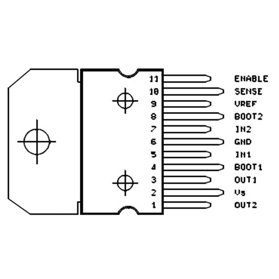
The L6203 is available in a Multiwatt15 package. Below is the pin configuration:
| Pin Number | Pin Name | Description |
|---|---|---|
| 1 | OUT1 | Output 1 for H-bridge A |
| 2 | VS | Supply voltage for the power stage |
| 3 | OUT2 | Output 2 for H-bridge A |
| 4 | GND | Ground connection |
| 5 | IN1 | Logic input 1 for H-bridge A |
| 6 | IN2 | Logic input 2 for H-bridge A |
| 7 | ENA | Enable pin for H-bridge A (active high) |
| 8 | ENB | Enable pin for H-bridge B (active high) |
| 9 | IN3 | Logic input 1 for H-bridge B |
| 10 | IN4 | Logic input 2 for H-bridge B |
| 11 | GND | Ground connection |
| 12 | OUT3 | Output 1 for H-bridge B |
| 13 | VS | Supply voltage for the power stage |
| 14 | OUT4 | Output 2 for H-bridge B |
| 15 | Vref | Reference voltage for current sensing (optional, connect to GND if unused) |
Usage Instructions
How to Use the L6203 in a Circuit
- Power Supply: Connect the supply voltage (12V to 48V) to the
VSpins (pins 2 and 13). Ensure the power supply can handle the current requirements of your motor. - Motor Connections: Connect the motor terminals to the output pins (
OUT1,OUT2for H-bridge A orOUT3,OUT4for H-bridge B). - Logic Inputs: Use the
IN1,IN2,IN3, andIN4pins to control the direction of the motors. These pins accept standard logic levels (0V for LOW, 5V for HIGH). - Enable Pins: Set the
ENAandENBpins HIGH to enable the respective H-bridges. Pull these pins LOW to disable the H-bridges. - PWM Control: Apply a PWM signal to the logic input pins (
IN1,IN2,IN3,IN4) to control motor speed. - Current Sensing (Optional): If current sensing is required, connect a resistor between the
Vrefpin and ground. The voltage across this resistor will be proportional to the motor current.
Important Considerations
- Heat Dissipation: The L6203 can generate significant heat during operation. Use a heatsink or proper thermal management to prevent overheating.
- Decoupling Capacitors: Place a high-value electrolytic capacitor (e.g., 100 µF) and a low-value ceramic capacitor (e.g., 0.1 µF) close to the
VSpins to stabilize the power supply. - Protection Diodes: The L6203 includes internal freewheeling diodes for motor back-EMF protection. However, additional external diodes may be added for extra safety in high-current applications.
Example: Connecting the L6203 to an Arduino UNO
Below is an example of how to control a DC motor using the L6203 and an Arduino UNO:
Circuit Connections
- Connect
VSto a 12V power supply. - Connect
OUT1andOUT2to the motor terminals. - Connect
IN1andIN2to Arduino digital pins 9 and 10, respectively. - Connect
ENAto Arduino digital pin 8. - Connect
GNDto the Arduino GND.
Arduino Code
// Define pin connections
const int ENA = 8;  // Enable pin for H-bridge A
const int IN1 = 9;  // Logic input 1 for H-bridge A
const int IN2 = 10; // Logic input 2 for H-bridge A

void setup() {
  // Set pin modes
  pinMode(ENA, OUTPUT);
  pinMode(IN1, OUTPUT);
  pinMode(IN2, OUTPUT);

  // Enable the H-bridge
  digitalWrite(ENA, HIGH);
}

void loop() {
  // Rotate motor in one direction
  digitalWrite(IN1, HIGH);
  digitalWrite(IN2, LOW);
  delay(2000); // Run for 2 seconds

  // Stop the motor
  digitalWrite(IN1, LOW);
  digitalWrite(IN2, LOW);
  delay(1000); // Pause for 1 second

  // Rotate motor in the opposite direction
  digitalWrite(IN1, LOW);
  digitalWrite(IN2, HIGH);
  delay(2000); // Run for 2 seconds

  // Stop the motor
  digitalWrite(IN1, LOW);
  digitalWrite(IN2, LOW);
  delay(1000); // Pause for 1 second
}
Troubleshooting and FAQs
Common Issues
Motor Not Spinning
- Ensure the
ENApin is set HIGH to enable the H-bridge. - Verify the power supply voltage and current are sufficient for the motor.
- Check the logic input connections (
IN1,IN2, etc.) and ensure they are receiving the correct signals.
- Ensure the
Overheating
- Use a heatsink or active cooling to manage heat dissipation.
- Reduce the motor load or operating current if possible.
Erratic Motor Behavior
- Add decoupling capacitors near the
VSpins to stabilize the power supply. - Check for loose or faulty connections in the circuit.
- Add decoupling capacitors near the
FAQs
Q: Can the L6203 drive two DC motors simultaneously?
A: Yes, the L6203 has two H-bridges, allowing it to drive two DC motors independently.
Q: What is the maximum PWM frequency supported?
A: The L6203 supports PWM frequencies up to 100 kHz.
Q: Do I need external diodes for motor back-EMF protection?
A: The L6203 includes internal freewheeling diodes, but external diodes can be added for additional protection in high-current applications.