How to Use Modulo Led 2 Colores 5mm : Examples, Pinouts, and Specs
Introduction
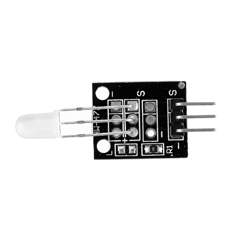
The Modulo Led 2 Colores 5mm (KY-011), manufactured by Keys, is a dual-color LED module designed for use in a variety of electronic projects. This module features a 5mm LED capable of emitting two distinct colors, typically red and green, depending on the applied voltage and polarity. It is commonly used as a visual indicator in circuits, providing status updates, alerts, or other signals.
Explore Projects Built with Modulo Led 2 Colores 5mm
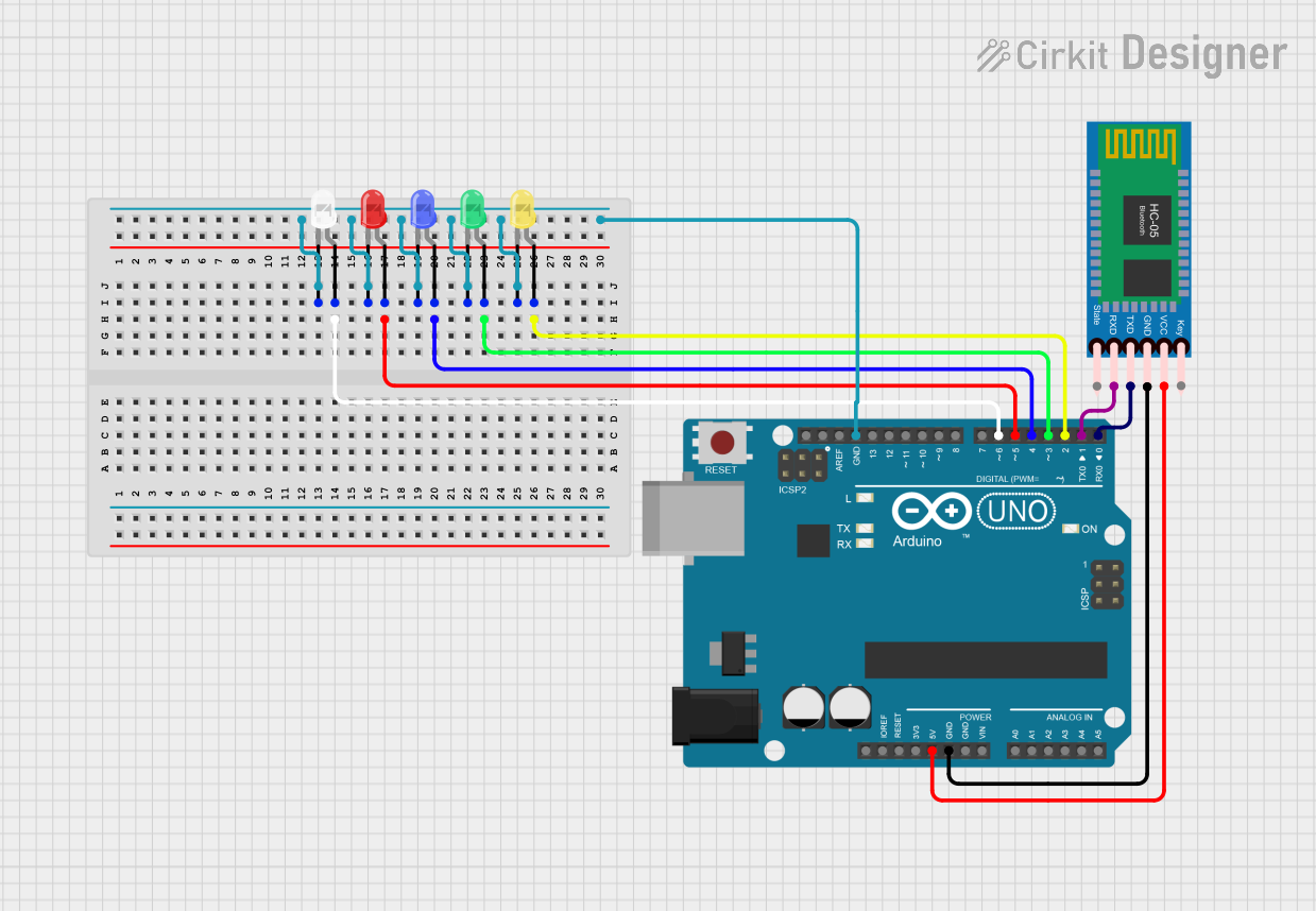

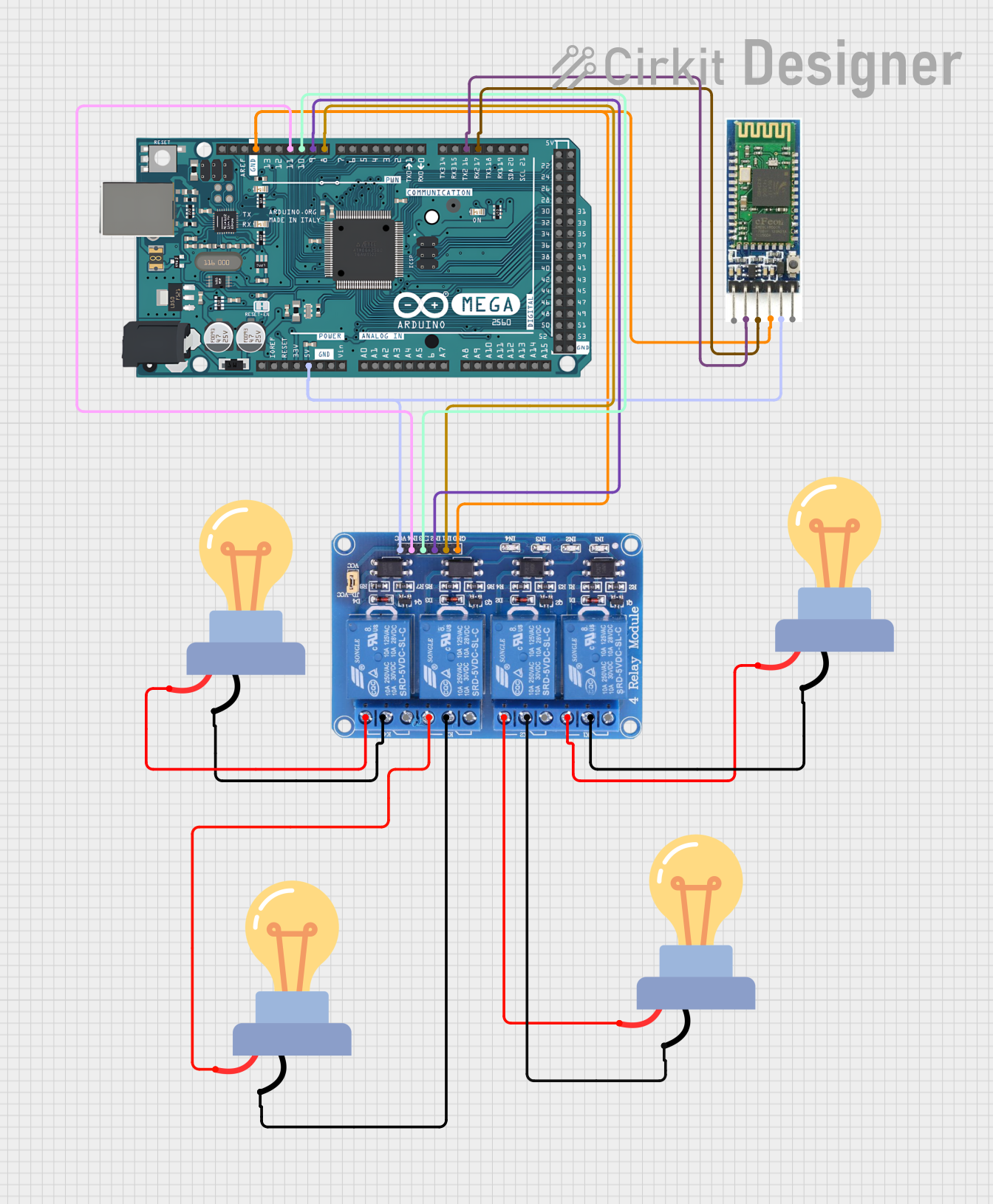
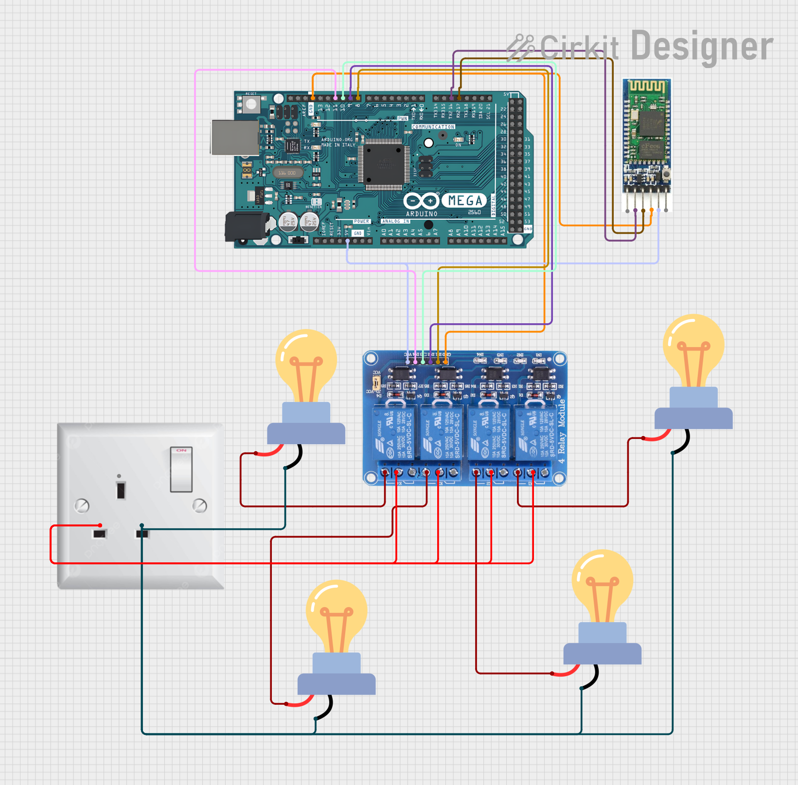
Explore Projects Built with Modulo Led 2 Colores 5mm
Common Applications
- Status indicators in electronic devices
- Signal lights in DIY projects
- Visual feedback in Arduino-based systems
- Educational and prototyping purposes
Technical Specifications
The following table outlines the key technical details of the KY-011 module:
| Parameter | Value |
|---|---|
| LED Type | 5mm Dual-Color (Red/Green) |
| Operating Voltage | 2.0V (Red), 3.0V (Green) |
| Forward Current | 20mA (typical) |
| Module Dimensions | 18mm x 10mm x 8mm |
| Connector Type | 3-pin header |
| Manufacturer Part ID | KY-011 |
Pin Configuration
The KY-011 module has a 3-pin header for easy connection. The pinout is as follows:
| Pin | Name | Description |
|---|---|---|
| 1 | Signal 1 | Controls the red LED (active HIGH) |
| 2 | GND | Ground connection (common cathode) |
| 3 | Signal 2 | Controls the green LED (active HIGH) |
Usage Instructions
How to Use the KY-011 in a Circuit
Connect the Pins:
- Connect the GND pin of the module to the ground of your power supply or microcontroller.
- Connect Signal 1 to a digital output pin of your microcontroller to control the red LED.
- Connect Signal 2 to another digital output pin to control the green LED.
Power Requirements:
- Ensure the operating voltage does not exceed the specified limits (2.0V for red, 3.0V for green).
- Use current-limiting resistors (typically 220Ω to 330Ω) in series with the signal pins to prevent damage to the LEDs.
Control Logic:
- Set the corresponding signal pin HIGH to turn on the desired LED color.
- Both LEDs can be turned on simultaneously to produce a mixed color (e.g., yellow).
Example Arduino Code
Below is an example of how to use the KY-011 module with an Arduino UNO:
// Define the pins connected to the KY-011 module
const int redPin = 8;   // Pin controlling the red LED
const int greenPin = 9; // Pin controlling the green LED

void setup() {
  // Set the LED pins as outputs
  pinMode(redPin, OUTPUT);
  pinMode(greenPin, OUTPUT);
}

void loop() {
  // Turn on the red LED
  digitalWrite(redPin, HIGH);
  digitalWrite(greenPin, LOW);
  delay(1000); // Keep red LED on for 1 second

  // Turn on the green LED
  digitalWrite(redPin, LOW);
  digitalWrite(greenPin, HIGH);
  delay(1000); // Keep green LED on for 1 second

  // Turn on both LEDs to produce yellow
  digitalWrite(redPin, HIGH);
  digitalWrite(greenPin, HIGH);
  delay(1000); // Keep both LEDs on for 1 second

  // Turn off both LEDs
  digitalWrite(redPin, LOW);
  digitalWrite(greenPin, LOW);
  delay(1000); // Keep LEDs off for 1 second
}
Important Considerations
- Always use appropriate current-limiting resistors to protect the LEDs.
- Avoid exceeding the maximum forward current (20mA) to prevent damage.
- Ensure proper grounding to avoid erratic behavior.
Troubleshooting and FAQs
Common Issues and Solutions
LEDs Do Not Light Up:
- Verify the connections to the signal and ground pins.
- Check if the current-limiting resistors are properly connected.
- Ensure the microcontroller pins are set as outputs and are providing the correct voltage.
Only One Color Lights Up:
- Confirm that both signal pins are connected to the microcontroller.
- Test the module with a multimeter to ensure both LEDs are functional.
LEDs Are Dim:
- Check the value of the current-limiting resistors. Resistors with too high a value can reduce brightness.
- Ensure the power supply voltage is sufficient.
Mixed Colors Are Not Achieved:
- Verify that both signal pins are set HIGH simultaneously.
- Ensure the LEDs are not damaged or improperly connected.
FAQs
Q: Can I use the KY-011 module without a microcontroller?
A: Yes, you can connect the signal pins to a power source (with resistors) to manually control the LEDs.
Q: What happens if I reverse the polarity?
A: The LEDs will not light up, but no damage will occur as long as the voltage is within safe limits.
Q: Can I use PWM to control brightness?
A: Yes, you can use PWM (Pulse Width Modulation) on the signal pins to adjust the brightness of the LEDs.
This concludes the documentation for the Modulo Led 2 Colores 5mm (KY-011).