How to Use SSR: Examples, Pinouts, and Specs
Introduction
A Solid State Relay (SSR) is an electronic switching device that uses semiconductor components, such as thyristors, triacs, or transistors, to perform switching operations. Unlike traditional electromechanical relays, SSRs have no moving parts, which allows for faster switching speeds, silent operation, and a significantly longer lifespan. SSRs are ideal for applications requiring high reliability and frequent switching.
Explore Projects Built with SSR


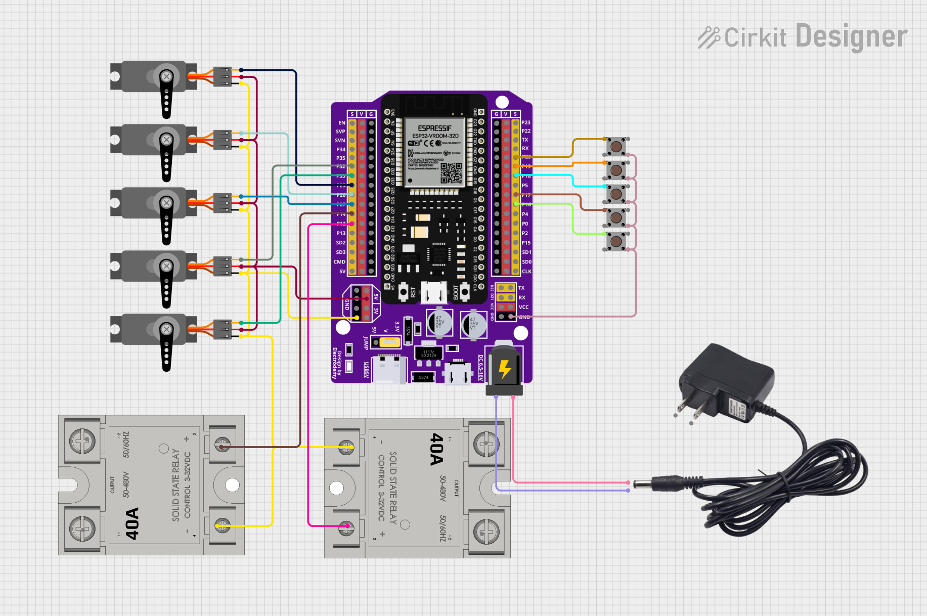
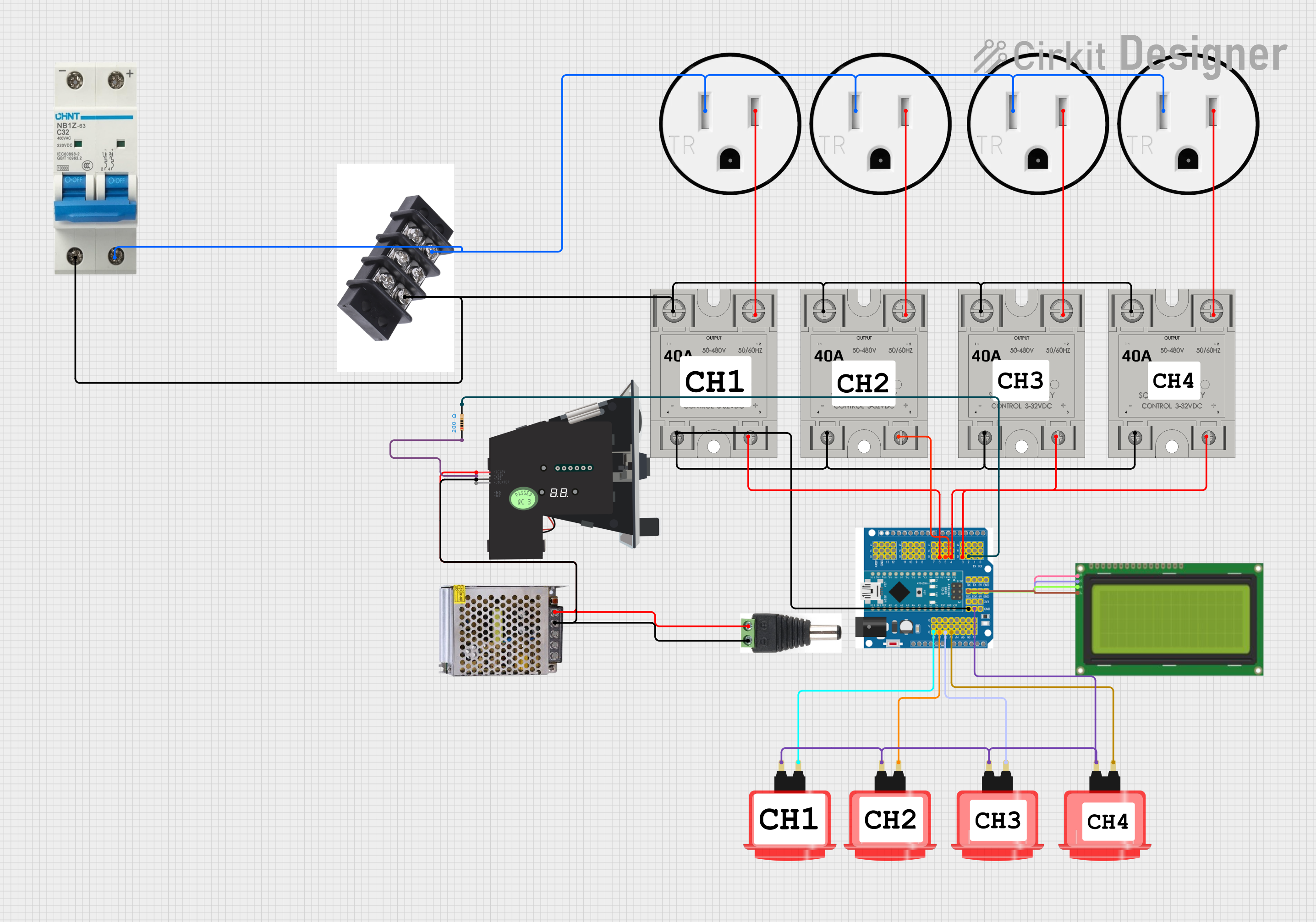
Explore Projects Built with SSR
Common Applications and Use Cases
- Industrial automation and control systems
- Heating, ventilation, and air conditioning (HVAC) systems
- Motor control and lighting systems
- Home appliances and smart home devices
- Power distribution and load management
Technical Specifications
Below are the key technical details for the Arduino AC-DC Solid State Relay (SSR):
General Specifications
| Parameter | Value |
|---|---|
| Manufacturer | Arduino |
| Part ID | AC-DC |
| Switching Type | AC and DC loads |
| Control Voltage Range | 3V to 32V DC |
| Load Voltage Range | 24V to 380V AC / 0V to 100V DC |
| Load Current Rating | Up to 25A |
| Isolation Voltage | 2500V AC |
| Switching Speed | < 10 ms |
| Operating Temperature | -30°C to +80°C |
| Mounting Type | Panel Mount |
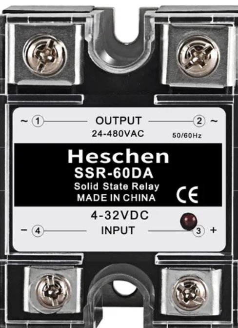
Pin Configuration and Descriptions
The SSR typically has four terminals, as described below:
| Pin Number | Name | Description |
|---|---|---|
| 1 | Input (+) | Positive control signal input (3V to 32V DC) |
| 2 | Input (-) | Negative control signal input (ground) |
| 3 | Load Terminal | Connect to one side of the AC or DC load |
| 4 | Load Terminal | Connect to the other side of the AC or DC load |
Usage Instructions
How to Use the SSR in a Circuit
- Control Signal Connection: Connect the control signal (e.g., from a microcontroller like Arduino UNO) to the input terminals of the SSR. Ensure the control voltage is within the specified range (3V to 32V DC).
- Load Connection: Connect the load (e.g., motor, light, or heater) to the load terminals of the SSR. Ensure the load voltage and current are within the SSR's rated specifications.
- Power Supply: Provide an appropriate power supply to the load circuit.
- Switching: When the control signal is applied, the SSR will switch the load circuit on or off.
Important Considerations and Best Practices
- Heat Dissipation: SSRs can generate heat during operation. Use a heat sink or proper ventilation to prevent overheating.
- Snubber Circuit: For inductive loads, use a snubber circuit to protect the SSR from voltage spikes.
- Isolation: Ensure proper electrical isolation between the control and load circuits to prevent damage to the control system.
- Polarity: Observe correct polarity when connecting the control signal to avoid malfunction or damage.
Example: Connecting an SSR to an Arduino UNO
Below is an example of how to control an SSR using an Arduino UNO to switch an AC load (e.g., a light bulb):
Circuit Diagram
- Connect the SSR's input terminals to the Arduino UNO:
- Input (+) to Arduino digital pin 9
- Input (-) to Arduino GND
- Connect the AC load (e.g., a light bulb) to the SSR's load terminals.
- Ensure the AC power supply is connected to the load circuit.
Arduino Code
// Define the pin connected to the SSR control input
const int ssrPin = 9;

void setup() {
  // Set the SSR pin as an output
  pinMode(ssrPin, OUTPUT);
}

void loop() {
  // Turn the SSR (and the connected load) ON
  digitalWrite(ssrPin, HIGH);
  delay(5000); // Keep the load ON for 5 seconds

  // Turn the SSR (and the connected load) OFF
  digitalWrite(ssrPin, LOW);
  delay(5000); // Keep the load OFF for 5 seconds
}
Troubleshooting and FAQs
Common Issues and Solutions
SSR Not Switching the Load
- Cause: Insufficient control voltage or incorrect wiring.
- Solution: Verify the control voltage is within the specified range (3V to 32V DC). Check the wiring for proper connections.
Overheating
- Cause: Excessive load current or inadequate heat dissipation.
- Solution: Ensure the load current does not exceed the SSR's rated capacity. Use a heat sink or improve ventilation.
Load Not Turning Off Completely
- Cause: Leakage current in the SSR.
- Solution: Use a load resistor to dissipate the leakage current, especially for low-power loads.
Noise or Interference in the Control Circuit
- Cause: Electrical noise or improper grounding.
- Solution: Use shielded cables for the control signal and ensure proper grounding.
FAQs
Q: Can the SSR be used for both AC and DC loads?
A: Yes, the Arduino AC-DC SSR supports both AC and DC loads within the specified voltage and current ranges.
Q: Is the SSR polarity-sensitive?
A: The control input is polarity-sensitive, so ensure correct polarity when connecting the control signal. The load terminals are not polarity-sensitive for AC loads but must be correctly connected for DC loads.
Q: How do I protect the SSR from voltage spikes?
A: Use a snubber circuit or a varistor across the load terminals to suppress voltage spikes, especially for inductive loads.
Q: Can I use the SSR for high-frequency switching?
A: SSRs are suitable for relatively high switching speeds, but for very high-frequency applications, consider using MOSFETs or IGBTs instead.