
How to Use Power Jack: Examples, Pinouts, and Specs
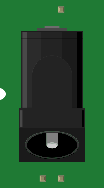
 Design with Power Jack in Cirkit Designer
Introduction
A Power Jack is a socket designed to connect an external power supply to an electronic circuit. It serves as a reliable interface for delivering the required voltage and current to power various devices. Power Jacks are commonly used in consumer electronics, development boards, and embedded systems to provide a stable power source.
Explore Projects Built with Power Jack
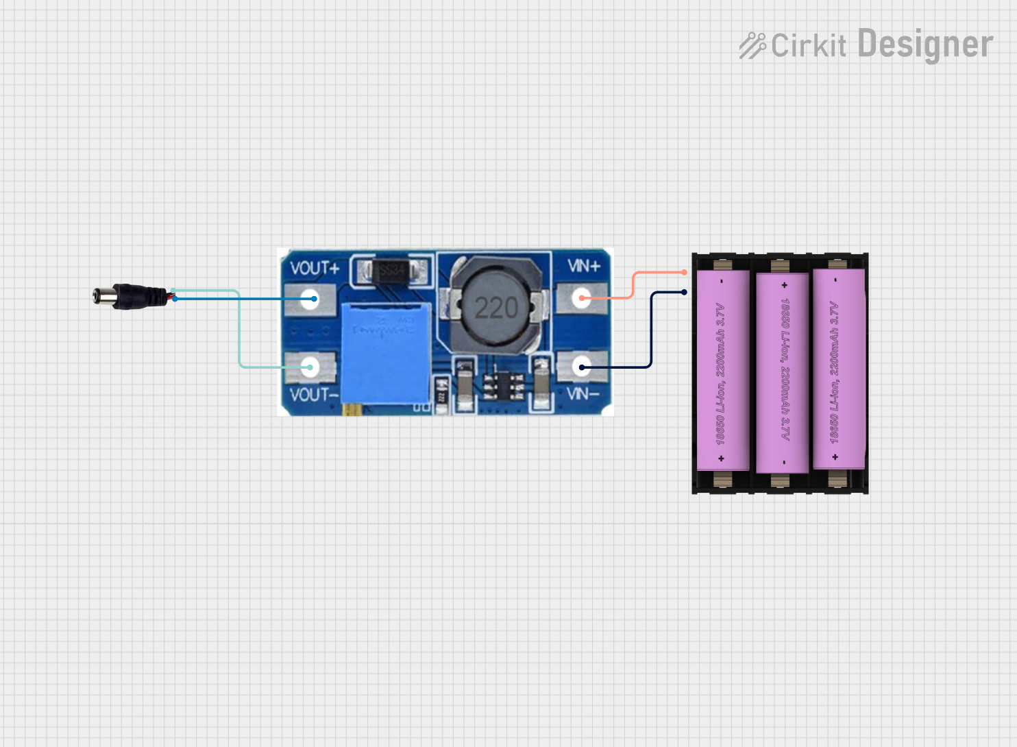 Open Project in Cirkit Designer
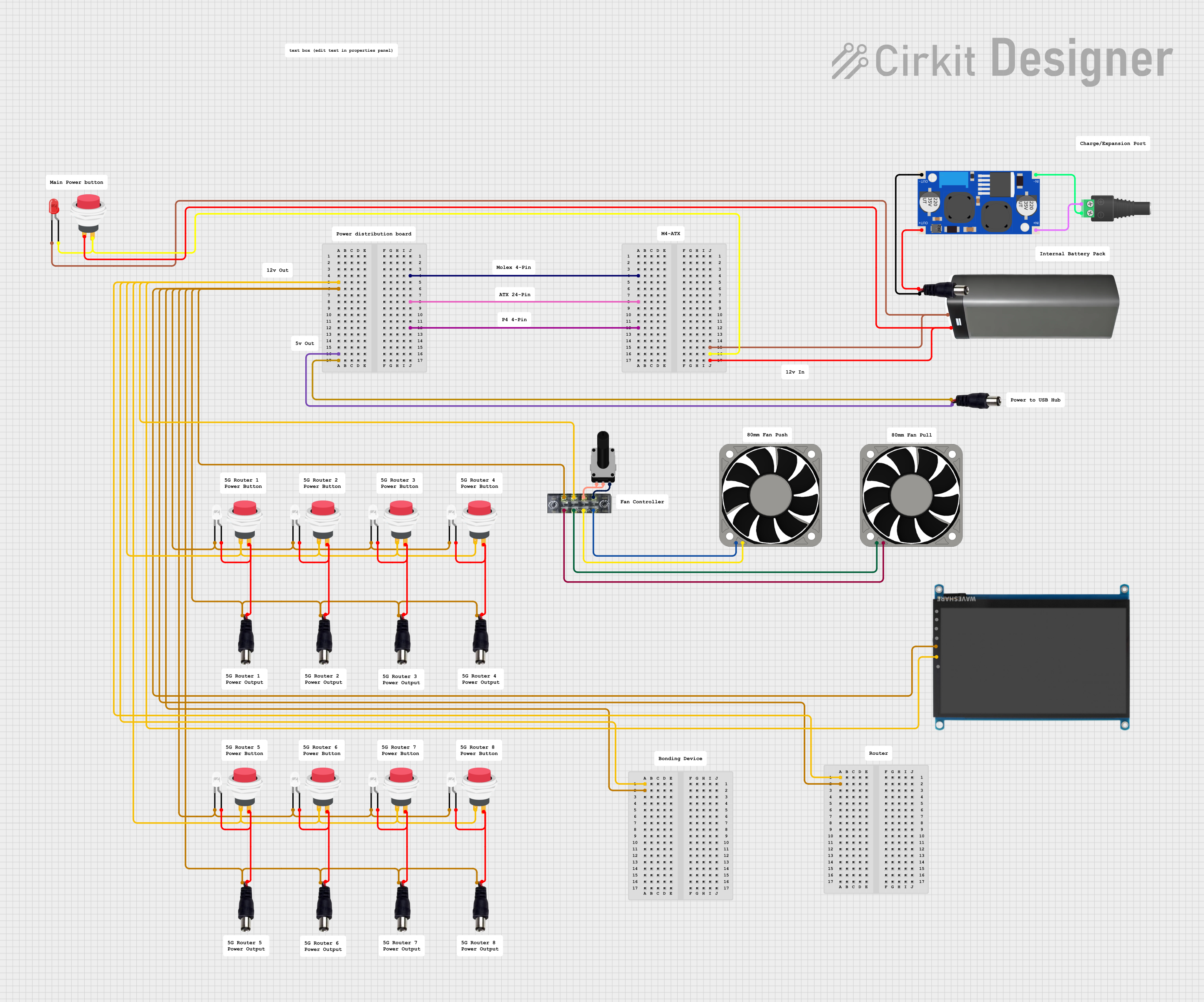 Open Project in Cirkit Designer
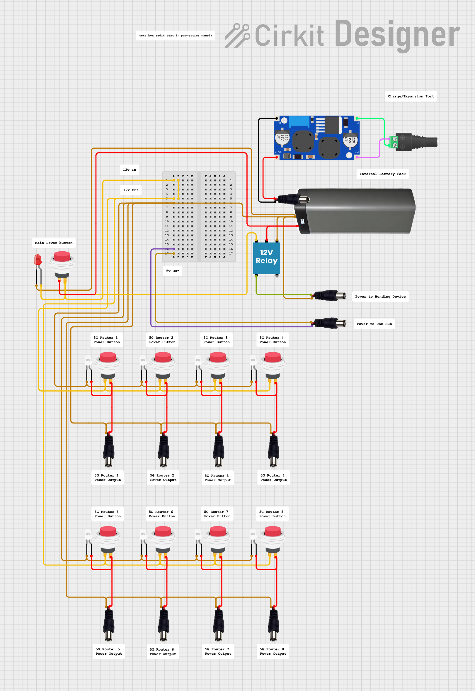 Open Project in Cirkit Designer
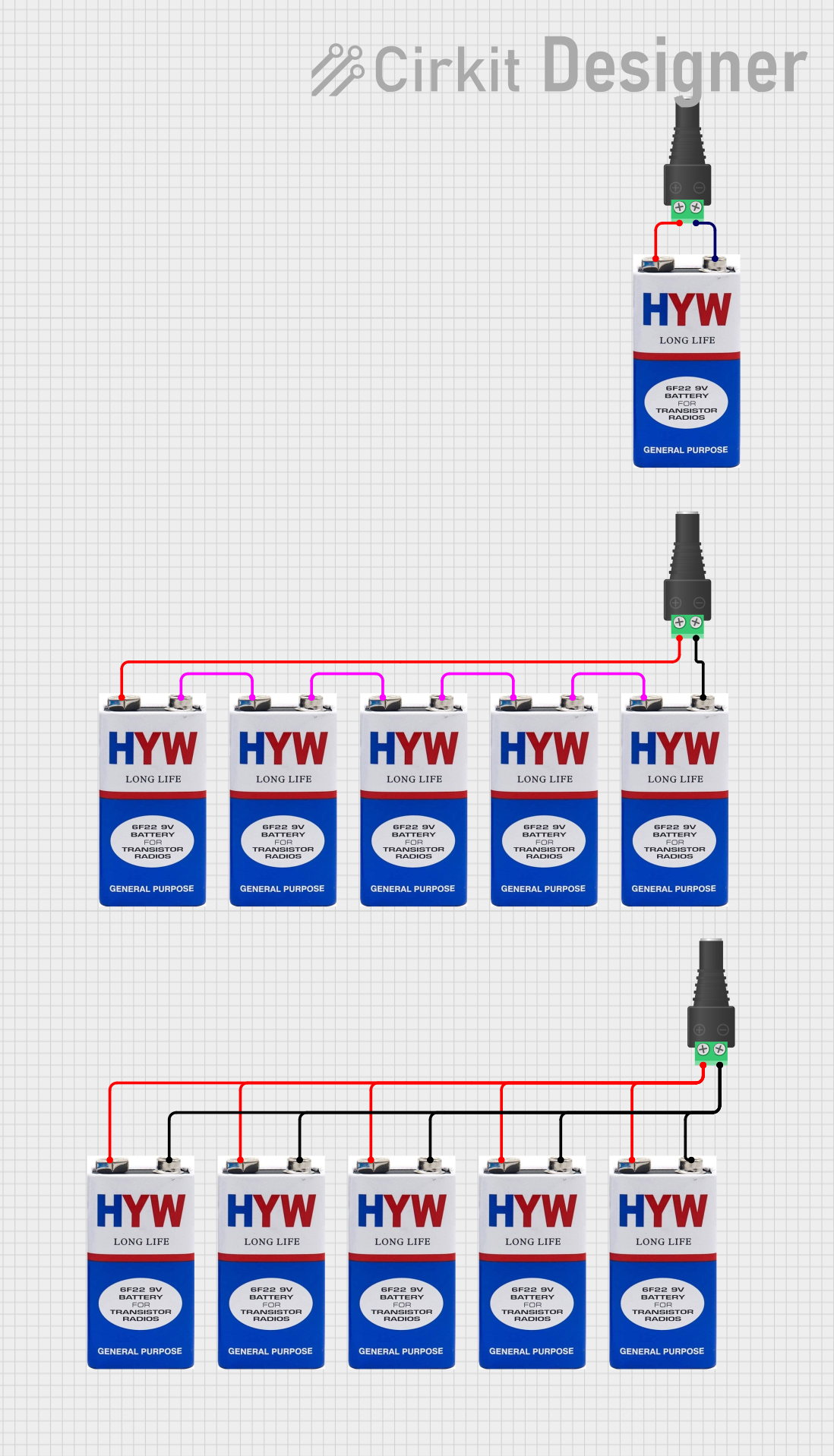 Open Project in Cirkit Designer
Explore Projects Built with Power Jack
Open Project in Cirkit DesignerOpen Project in Cirkit DesignerOpen Project in Cirkit DesignerOpen Project in Cirkit DesignerCommon Applications and Use Cases
- Powering development boards like Arduino, Raspberry Pi, and other microcontrollers.
- Supplying power to consumer electronics such as laptops, routers, and audio equipment.
- Used in DIY electronics projects for easy connection to external power supplies.
- Providing a secure and detachable power connection in industrial and commercial devices.
Technical Specifications
Key Technical Details
- Voltage Rating: Typically supports 3V to 24V (check specific model for exact range).
- Current Rating: Commonly supports up to 5A (varies by model).
- Connector Type: Barrel-style connector (e.g., 2.1mm or 2.5mm inner diameter).
- Polarity: Center pin is usually positive (+), and the outer sleeve is negative (-).
- Mounting Style: Panel mount or PCB mount.
- Material: Metal contacts with plastic or metal housing.
Pin Configuration and Descriptions
The Power Jack typically has three pins for connection:
| Pin Name | Description |
|---|---|
| Positive (VCC) | Connects to the positive terminal of the power supply (center pin of the jack). |
| Negative (GND) | Connects to the ground terminal of the power supply (outer sleeve of the jack). |
| Switch Pin | Optional pin used to detect the presence of a plug or to disconnect internal power. |
Note: Not all Power Jacks include a switch pin. Check the datasheet for your specific model.
Usage Instructions
How to Use the Power Jack in a Circuit
- Identify the Pinout: Determine the positive (VCC), negative (GND), and switch pin (if available) using the datasheet or a multimeter.
- Connect to Power Source:
- Ensure the power supply matches the voltage and current requirements of your circuit.
- Verify the polarity of the power supply matches the Power Jack's configuration.
- Soldering:
- For PCB-mounted Power Jacks, solder the pins to the corresponding pads on the PCB.
- For panel-mounted Power Jacks, secure the jack to the panel and connect wires to the pins.
- Test the Connection:
- Use a multimeter to confirm proper voltage and polarity at the output terminals before powering the circuit.
Important Considerations and Best Practices
- Polarity Check: Always verify the polarity of the power supply to avoid damaging your circuit.
- Current Rating: Ensure the Power Jack can handle the maximum current required by your circuit.
- Secure Mounting: For panel-mounted jacks, use a locking nut to prevent movement or disconnection.
- Heat Management: Avoid exceeding the rated current to prevent overheating of the Power Jack.
- Switch Pin Usage: If your Power Jack includes a switch pin, you can use it to automatically disconnect an internal battery when an external power supply is connected.
Example: Connecting a Power Jack to an Arduino UNO
The Arduino UNO can be powered using a 2.1mm barrel jack. Below is an example of how to connect and use it:
- Connect a 9V DC power adapter with a 2.1mm barrel plug to the Power Jack.
- Ensure the adapter's center pin is positive and the outer sleeve is negative.
- Plug the Power Jack into the Arduino UNO's barrel jack input.
Arduino Code Example
If you want to monitor the external power supply voltage using an analog pin, you can use the following code:
// This code reads the voltage from an analog pin and displays it via Serial Monitor.
// Ensure the voltage divider circuit is used to step down the voltage to a safe level.

const int voltagePin = A0; // Analog pin connected to the voltage divider output
float voltage = 0.0;

void setup() {
  Serial.begin(9600); // Initialize serial communication at 9600 baud
}

void loop() {
  int sensorValue = analogRead(voltagePin); // Read the analog input
  voltage = sensorValue * (5.0 / 1023.0);   // Convert to voltage (assuming 5V reference)

  // Print the voltage to the Serial Monitor
  Serial.print("Voltage: ");
  Serial.print(voltage);
  Serial.println(" V");

  delay(1000); // Wait for 1 second before the next reading
}
Note: Use a voltage divider circuit if the input voltage exceeds the Arduino's 5V limit.
Troubleshooting and FAQs
Common Issues and Solutions
| Issue | Possible Cause | Solution |
|---|---|---|
| No power to the circuit | Incorrect polarity or loose connection | Verify the polarity and ensure all connections are secure. |
| Overheating of the Power Jack | Exceeding current rating | Use a Power Jack with a higher current rating or reduce the circuit's load. |
| Circuit not switching to external power | Switch pin not connected or configured incorrectly | Check the switch pin connection and ensure proper wiring. |
| Voltage drop across the Power Jack | Poor contact or low-quality Power Jack | Use a high-quality Power Jack and ensure proper soldering or connections. |
FAQs
Can I use a Power Jack for AC power?
- No, Power Jacks are typically designed for DC power. Using AC power may damage the component or connected devices.
What happens if I reverse the polarity?
- Reversing the polarity can damage your circuit. Use a diode or polarity protection circuit to prevent this.
How do I choose the right Power Jack for my project?
- Consider the voltage, current rating, and connector size. Ensure compatibility with your power supply and circuit requirements.
Can I use a Power Jack without the switch pin?
- Yes, the switch pin is optional and not required for basic power delivery. It is used for advanced features like switching between power sources.
By following this documentation, you can effectively integrate a Power Jack into your electronic projects while ensuring safety and reliability.