How to Use I2C BMI160: Examples, Pinouts, and Specs
Introduction
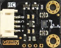
The I2C BMI160 is a state-of-the-art 6-Axis Inertial Motion Sensor that combines a 3-axis accelerometer and a 3-axis gyroscope into a single package. Manufactured by DFRobot, this sensor is designed for motion tracking in a wide array of applications including robotics, drones, wearable devices, and gaming. Its small form factor and low power consumption make it ideal for battery-powered or space-constrained devices.
Explore Projects Built with I2C BMI160
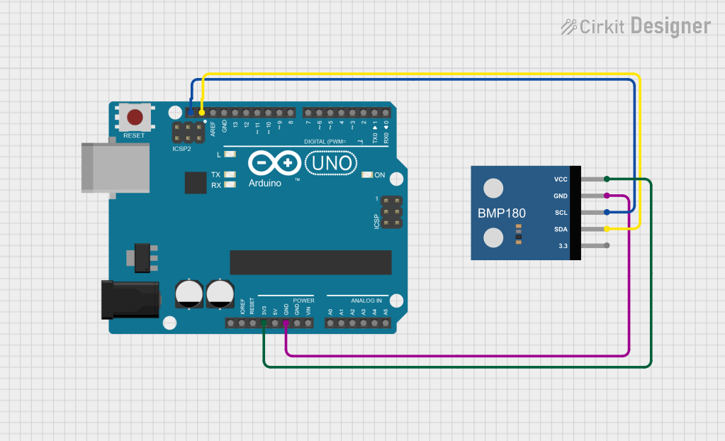
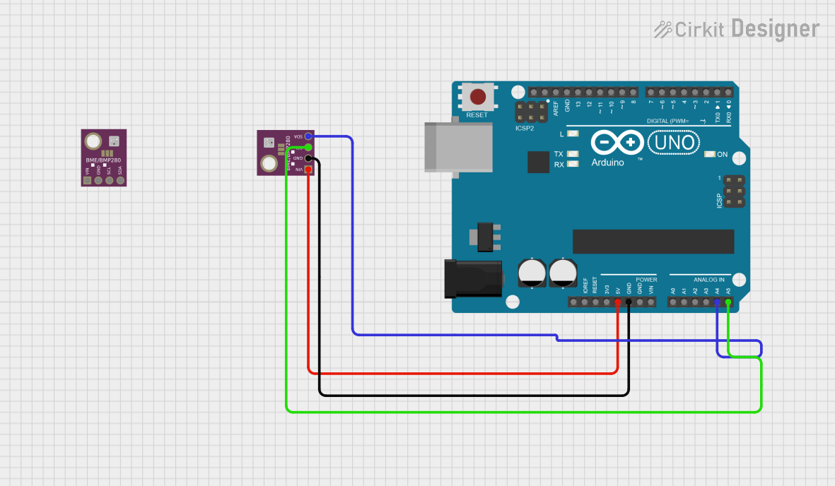
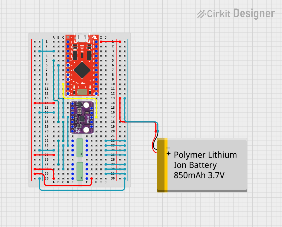
Explore Projects Built with I2C BMI160
Technical Specifications
Key Features
- Accelerometer: 3-axis, ±2g/±4g/±8g/±16g selectable
- Gyroscope: 3-axis, ±125°/s to ±2000°/s selectable
- Interface: I2C (up to 3.4 MHz)
- Supply Voltage (VDD): 2.4V to 3.6V
- Input Voltage (VDDIO): 1.2V to 3.6V
- Current Consumption: 950 μA (full operation)
- Temperature Range: -40°C to +85°C
- Sensitivity (configurable):
- Accelerometer: 16384 LSB/g @ ±2g to 2048 LSB/g @ ±16g
- Gyroscope: 16.4 LSB/°/s @ ±125°/s to 131 LSB/°/s @ ±2000°/s
Pin Configuration and Descriptions
| Pin Number | Name | Description |
|---|---|---|
| 1 | VDD | Power supply voltage (2.4V to 3.6V) |
| 2 | GND | Ground reference for power supply |
| 3 | SCL | I2C clock line |
| 4 | SDA | I2C data line |
| 5 | INT1 | Interrupt output 1 (configurable) |
| 6 | INT2 | Interrupt output 2 (configurable) |
| 7 | CS | Chip select for SPI interface (not used for I2C) |
| 8 | AD0/SDO | I2C address selection or SPI data output |
Usage Instructions
Integration into a Circuit
To use the I2C BMI160 sensor in a circuit:
- Connect VDD to a 2.4V to 3.6V power supply.
- Connect GND to the ground of the power supply.
- Connect SCL and SDA to the I2C clock and data lines, respectively.
- Optionally, connect INT1 and INT2 to microcontroller pins if interrupt features are needed.
Best Practices
- Use pull-up resistors on the SCL and SDA lines, typically 4.7kΩ to 10kΩ.
- Keep the I2C lines as short as possible to reduce noise and improve communication reliability.
- Ensure that the power supply is stable and within the specified voltage range.
- If multiple I2C devices are on the same bus, ensure that each device has a unique address.
Arduino UNO Example Code
#include <Wire.h>

// BMI160 I2C address (check AD0/SDO pin for address configuration)
const int BMI160_I2C_ADDR = 0x68;

void setup() {
  Wire.begin(); // Initialize I2C
  Serial.begin(9600); // Start serial communication at 9600 baud rate

  // Initialize BMI160 (basic initialization code, further configuration may be required)
  Wire.beginTransmission(BMI160_I2C_ADDR);
  // Write to a register, for example, to reset the device
  Wire.write(0x7E); // Command register address
  Wire.write(0xB6); // Command to reset the device
  Wire.endTransmission();
  delay(100); // Wait for the reset to complete
}

void loop() {
  // Code to read data from the sensor
  // This is a placeholder for actual data reading and processing
}
Troubleshooting and FAQs
Common Issues
- No Data or Erratic Readings: Ensure that the I2C connections are secure and that the correct pull-up resistors are in place. Check for proper power supply voltage.
- Device Not Detected: Verify that the I2C address is correct and that there are no address conflicts on the I2C bus.
- Inaccurate Readings: Calibrate the sensor as per the manufacturer's instructions and ensure that it is placed on a stable surface away from magnetic fields.
FAQs
Q: Can the BMI160 be used with both 3.3V and 5V microcontrollers? A: Yes, the BMI160 can interface with both 3.3V and 5V systems, but ensure that VDDIO is within the specified range for logic levels.
Q: How can I change the I2C address of the BMI160? A: The I2C address can be changed by connecting the AD0/SDO pin to either high or low voltage levels.
Q: What is the purpose of the INT1 and INT2 pins? A: These pins can be configured to output interrupt signals for various events detected by the sensor, such as motion detection or data ready signals.
For further assistance, consult the manufacturer's datasheet and technical support resources.