How to Use 4 channel relay module 5V JD-VCC: Examples, Pinouts, and Specs
Introduction
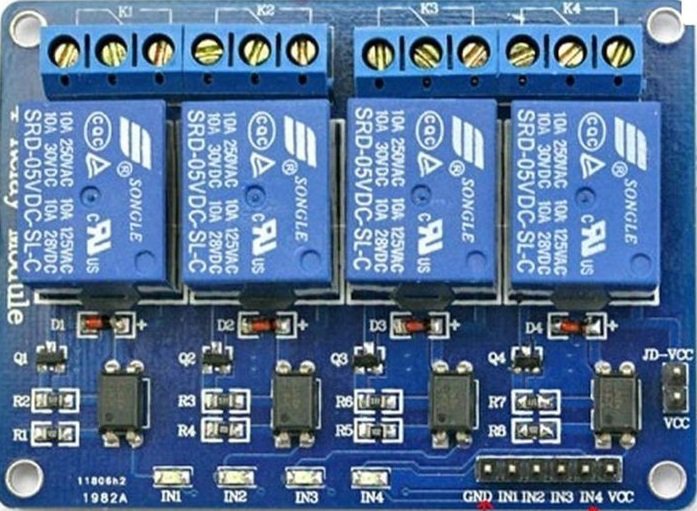
The 4 Channel Relay Module 5V JD-VCC is a versatile electronic component designed to control up to four independent devices using a 5V power supply. Manufactured by Electronics Hub (Part ID: Mega 2560), this module is equipped with opto-isolation for enhanced safety and reliability. It is commonly used to switch high-voltage loads (AC or DC) with low-voltage control signals, making it ideal for home automation, industrial control systems, and IoT applications.
Explore Projects Built with 4 channel relay module 5V JD-VCC


Explore Projects Built with 4 channel relay module 5V JD-VCC
Common Applications
- Home automation systems (e.g., controlling lights, fans, or appliances)
- Industrial equipment control
- IoT projects requiring high-voltage switching
- Robotics and motor control
- Smart energy management systems
Technical Specifications
The following table outlines the key technical details of the 4 Channel Relay Module:
| Parameter | Specification |
|---|---|
| Operating Voltage | 5V DC |
| Trigger Voltage | 3.3V to 5V DC |
| Relay Type | Electromechanical |
| Maximum Load (AC) | 250V AC @ 10A |
| Maximum Load (DC) | 30V DC @ 10A |
| Isolation Type | Opto-isolated |
| Number of Channels | 4 |
| Dimensions | 75mm x 55mm x 20mm |
| Weight | ~60g |
Pin Configuration and Descriptions
The module has two sets of pins: Input Pins for control signals and Relay Output Terminals for connecting external devices.
Input Pins
| Pin Name | Description |
|---|---|
| VCC | 5V power supply input for the relay module |
| GND | Ground connection |
| IN1 | Control signal for Relay 1 (Active LOW) |
| IN2 | Control signal for Relay 2 (Active LOW) |
| IN3 | Control signal for Relay 3 (Active LOW) |
| IN4 | Control signal for Relay 4 (Active LOW) |
| JD-VCC | Jumper pin for relay power isolation (optional) |
Relay Output Terminals
Each relay has three output terminals:
| Terminal | Description |
|---|---|
| NO (Normally Open) | Open circuit when the relay is inactive |
| NC (Normally Closed) | Closed circuit when the relay is inactive |
| COM (Common) | Common terminal for NO and NC connections |
Usage Instructions
How to Use the Module in a Circuit
- Power the Module: Connect the VCC pin to a 5V DC power supply and the GND pin to ground.
- Control Signals: Use digital output pins from a microcontroller (e.g., Arduino UNO) to send control signals to the IN1, IN2, IN3, and IN4 pins. A LOW signal activates the corresponding relay.
- Connect External Devices:
- For each relay, connect the device's power line to the COM terminal.
- Use the NO terminal if you want the device to be OFF by default and turn ON when the relay is activated.
- Use the NC terminal if you want the device to be ON by default and turn OFF when the relay is activated.
- Isolation (Optional): If you want to isolate the relay power supply from the control circuit, remove the JD-VCC jumper and provide a separate 5V power supply to the JD-VCC pin.
Important Considerations
- Opto-Isolation: Ensure the opto-isolation feature is used when working with high-voltage loads to protect the control circuit.
- Load Ratings: Do not exceed the maximum load ratings (250V AC @ 10A or 30V DC @ 10A) to avoid damage.
- Active LOW Logic: The relays are triggered by a LOW signal. Ensure your microcontroller outputs are configured accordingly.
- Separate Power Supply: For high-power applications, consider using a separate power supply for the relays to prevent voltage drops.
Example: Connecting to an Arduino UNO
Below is an example of how to control the 4 Channel Relay Module using an Arduino UNO:
Circuit Connections
- Connect the module's VCC pin to the Arduino's 5V pin and GND to GND.
- Connect IN1, IN2, IN3, and IN4 to Arduino digital pins 7, 6, 5, and 4, respectively.
- Connect an external device (e.g., a light bulb) to the COM and NO terminals of Relay 1.
Arduino Code
// Example code to control a 4 Channel Relay Module with Arduino UNO

// Define relay control pins
#define RELAY1 7  // Relay 1 connected to digital pin 7
#define RELAY2 6  // Relay 2 connected to digital pin 6
#define RELAY3 5  // Relay 3 connected to digital pin 5
#define RELAY4 4  // Relay 4 connected to digital pin 4

void setup() {
  // Set relay pins as outputs
  pinMode(RELAY1, OUTPUT);
  pinMode(RELAY2, OUTPUT);
  pinMode(RELAY3, OUTPUT);
  pinMode(RELAY4, OUTPUT);

  // Initialize all relays to OFF (HIGH state)
  digitalWrite(RELAY1, HIGH);
  digitalWrite(RELAY2, HIGH);
  digitalWrite(RELAY3, HIGH);
  digitalWrite(RELAY4, HIGH);
}

void loop() {
  // Turn on Relay 1
  digitalWrite(RELAY1, LOW);  // Activate Relay 1
  delay(1000);               // Wait for 1 second

  // Turn off Relay 1 and turn on Relay 2
  digitalWrite(RELAY1, HIGH); // Deactivate Relay 1
  digitalWrite(RELAY2, LOW);  // Activate Relay 2
  delay(1000);               // Wait for 1 second

  // Turn off Relay 2 and turn on Relay 3
  digitalWrite(RELAY2, HIGH); // Deactivate Relay 2
  digitalWrite(RELAY3, LOW);  // Activate Relay 3
  delay(1000);               // Wait for 1 second

  // Turn off Relay 3 and turn on Relay 4
  digitalWrite(RELAY3, HIGH); // Deactivate Relay 3
  digitalWrite(RELAY4, LOW);  // Activate Relay 4
  delay(1000);               // Wait for 1 second

  // Turn off all relays
  digitalWrite(RELAY4, HIGH); // Deactivate Relay 4
  delay(1000);               // Wait for 1 second
}
Troubleshooting and FAQs
Common Issues
- Relays Not Activating:
- Ensure the module is powered with a stable 5V supply.
- Verify that the control signals are correctly connected and configured as LOW to activate the relays.
- Voltage Drops:
- Use a separate power supply for the relays if the microcontroller cannot provide sufficient current.
- Device Not Switching:
- Check the wiring of the COM, NO, and NC terminals.
- Ensure the load does not exceed the relay's maximum ratings.
FAQs
Q: Can I use this module with a 3.3V microcontroller?
A: Yes, the module supports trigger voltages as low as 3.3V. However, ensure the VCC pin is still powered with 5V.
Q: What is the purpose of the JD-VCC jumper?
A: The JD-VCC jumper allows you to isolate the relay power supply from the control circuit. Remove the jumper and provide a separate 5V supply to JD-VCC for isolation.
Q: Can I control AC devices with this module?
A: Yes, the module can switch AC devices up to 250V at 10A. Ensure proper safety precautions when working with high voltages.