
How to Use DISPLAY 7S - 3 DIG: Examples, Pinouts, and Specs
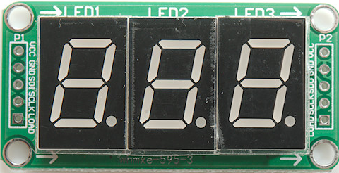
 Design with DISPLAY 7S - 3 DIG in Cirkit Designer
Introduction
The DISPLAY 7S - 3 DIG is a 3-digit seven-segment display designed to visually represent decimal numbers. Each digit is composed of seven individual LED segments arranged in a figure-eight pattern, allowing the display of numerals from 0 to 9. This component is widely used in digital clocks, counters, calculators, and other devices requiring numeric output.
Explore Projects Built with DISPLAY 7S - 3 DIG
 Open Project in Cirkit Designer
 Open Project in Cirkit Designer
 Open Project in Cirkit Designer
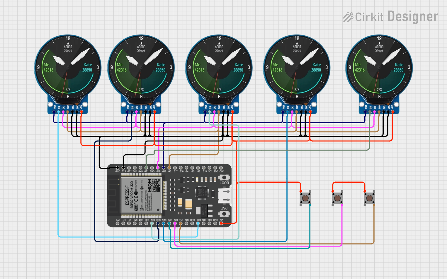
 Open Project in Cirkit Designer
Explore Projects Built with DISPLAY 7S - 3 DIG

 Open Project in Cirkit Designer
 Open Project in Cirkit Designer
 Open Project in Cirkit Designer
 Open Project in Cirkit Designer
Common Applications
- Digital clocks and timers
- Electronic counters
- Voltage or current meters
- Consumer electronics (e.g., microwave ovens, washing machines)
- Arduino-based projects for numeric displays
Technical Specifications
The following table outlines the key technical details of the DISPLAY 7S - 3 DIG:
| Parameter | Value |
|---|---|
| Operating Voltage | 2.0V - 3.3V (per segment) |
| Forward Current (If) | 10mA - 20mA (per segment) |
| Peak Forward Current | 100mA (per segment, <10ms) |
| Reverse Voltage (Vr) | 5V |
| Power Dissipation | 500mW |
| Common Type | Common Cathode or Anode |
| Number of Digits | 3 |
| Segment Color | Red (typical) |
| Viewing Angle | 120° |
Pin Configuration
The DISPLAY 7S - 3 DIG typically has 12 or 13 pins, depending on the manufacturer. Below is a general pinout for a common cathode configuration:
| Pin Number | Description |
|---|---|
| 1 | Segment E (Digit 1) |
| 2 | Segment D (Digit 1) |
| 3 | Segment C (Digit 1) |
| 4 | Common Cathode (Digit 1) |
| 5 | Segment B (Digit 1) |
| 6 | Segment A (Digit 1) |
| 7 | Common Cathode (Digit 2) |
| 8 | Segment F (Digit 2) |
| 9 | Segment G (Digit 2) |
| 10 | Segment A (Digit 2) |
| 11 | Segment B (Digit 2) |
| 12 | Common Cathode (Digit 3) |
| 13 | Segment DP (Decimal Point) |
Note: The exact pin configuration may vary depending on the manufacturer. Always refer to the datasheet for your specific model.
Usage Instructions
How to Use the Component in a Circuit
- Determine the Common Type: Identify whether the display is common cathode or common anode. This determines how the segments are activated.
- For a common cathode display, connect the cathode pins to ground.
- For a common anode display, connect the anode pins to the power supply.
- Connect Current-Limiting Resistors: To prevent damage to the LEDs, use resistors (typically 220Ω to 1kΩ) in series with each segment.
- Control the Segments: Use a microcontroller (e.g., Arduino) or a driver IC (e.g., 74HC595 shift register) to control the segments. Each segment is activated by applying the appropriate voltage.
Example Circuit with Arduino UNO
Below is an example of how to connect and control the DISPLAY 7S - 3 DIG using an Arduino UNO:
Circuit Connections
- Connect the common cathode pins of the display to GND.
- Connect each segment pin (A, B, C, D, E, F, G, DP) to Arduino digital pins through 220Ω resistors.
Arduino Code
// Define the pins connected to each segment of the display
const int segmentPins[] = {2, 3, 4, 5, 6, 7, 8, 9};
// A, B, C, D, E, F, G, DP

// Define the segment patterns for digits 0-9
const byte digitPatterns[] = {
  0b00111111, // 0
  0b00000110, // 1
  0b01011011, // 2
  0b01001111, // 3
  0b01100110, // 4
  0b01101101, // 5
  0b01111101, // 6
  0b00000111, // 7
  0b01111111, // 8
  0b01101111  // 9
};

void setup() {
  // Set all segment pins as outputs
  for (int i = 0; i < 8; i++) {
    pinMode(segmentPins[i], OUTPUT);
  }
}

void loop() {
  // Display digits 0-9 sequentially
  for (int digit = 0; digit < 10; digit++) {
    displayDigit(digit);
    delay(1000); // Wait 1 second before displaying the next digit
  }
}

// Function to display a single digit
void displayDigit(int digit) {
  byte pattern = digitPatterns[digit];
  for (int i = 0; i < 8; i++) {
    // Write HIGH or LOW to each segment based on the pattern
    digitalWrite(segmentPins[i], (pattern >> i) & 0x01);
  }
}
Important Considerations
- Power Supply: Ensure the power supply voltage matches the display's requirements.
- Resistors: Always use current-limiting resistors to protect the LEDs.
- Multiplexing: For multi-digit displays, consider using multiplexing to reduce the number of required control pins.
Troubleshooting and FAQs
Common Issues
- Segments Not Lighting Up:
- Check the connections and ensure the common cathode or anode is correctly connected.
- Verify that the current-limiting resistors are not too high.
- Dim Display:
- Ensure the power supply provides sufficient current.
- Check for loose or high-resistance connections.
- Incorrect Digits Displayed:
- Verify the segment-to-pin mapping in your code.
- Ensure the correct digit patterns are being sent to the display.
FAQs
Q: Can I use the display without a microcontroller?
A: Yes, you can use switches or a driver IC to control the segments manually, but a microcontroller provides more flexibility.
Q: How do I control the decimal point (DP)?
A: The DP segment is controlled like any other segment. Connect it to a digital pin and activate it as needed.
Q: Can I use this display for alphanumeric characters?
A: While primarily designed for numbers, some letters (e.g., A, b, C, d, E, F) can be displayed with creative segment activation.
By following this documentation, you can effectively integrate the DISPLAY 7S - 3 DIG into your projects and troubleshoot common issues.