How to Use Transistor: Examples, Pinouts, and Specs
Introduction
The transistor is a semiconductor device used to amplify or switch electronic signals and electrical power. It consists of three layers of semiconductor material, forming two junctions. Transistors are fundamental components in modern electronics, enabling the creation of amplifiers, switches, and digital logic circuits.
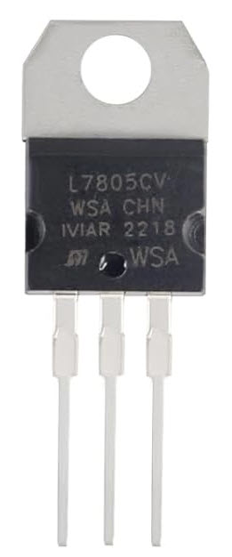
Manufactured by Professional Semiconductor Suppliers, the L7805 transistor is a versatile and reliable component suitable for a wide range of applications.
Explore Projects Built with Transistor

Explore Projects Built with Transistor
Common Applications and Use Cases
- Amplification of audio, radio, or other signals
- Switching operations in digital circuits
- Voltage regulation and power management
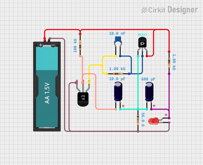
- Oscillators and signal modulation
- Used in microcontroller-based projects, including Arduino
Technical Specifications
Below are the key technical details for the L7805 transistor:
General Specifications
| Parameter | Value |
|---|---|
| Manufacturer | Professional Semiconductor Suppliers |
| Part ID | L7805 |
| Type | Bipolar Junction Transistor (BJT) |
| Configuration | NPN or PNP (varies by model) |
| Maximum Collector Current (Ic) | 1.5 A |
| Maximum Collector-Emitter Voltage (Vce) | 40 V |
| Maximum Power Dissipation (Pd) | 15 W |
| Gain (hFE) | 100 to 800 (varies by model) |
| Operating Temperature | -55°C to +150°C |
Pin Configuration and Descriptions
The L7805 transistor typically has three pins. The pinout is as follows:
| Pin Number | Name | Description |
|---|---|---|
| 1 | Collector (C) | Current flows out of this terminal in NPN mode. |
| 2 | Base (B) | Controls the transistor's operation by receiving a small current. |
| 3 | Emitter (E) | Current flows into this terminal in NPN mode. |
Note: Ensure you verify the pinout for your specific transistor model, as it may vary slightly.
Usage Instructions
How to Use the Transistor in a Circuit
- Identify the Pinout: Use the table above to correctly identify the collector, base, and emitter pins.
- Connect the Base: Apply a small current to the base pin to control the transistor's operation. For an NPN transistor, the base voltage must be higher than the emitter voltage.
- Connect the Collector and Emitter: The collector is connected to the positive voltage supply (for NPN), and the emitter is connected to the load or ground.
- Use a Resistor: Always use a base resistor to limit the current flowing into the base pin and prevent damage to the transistor.
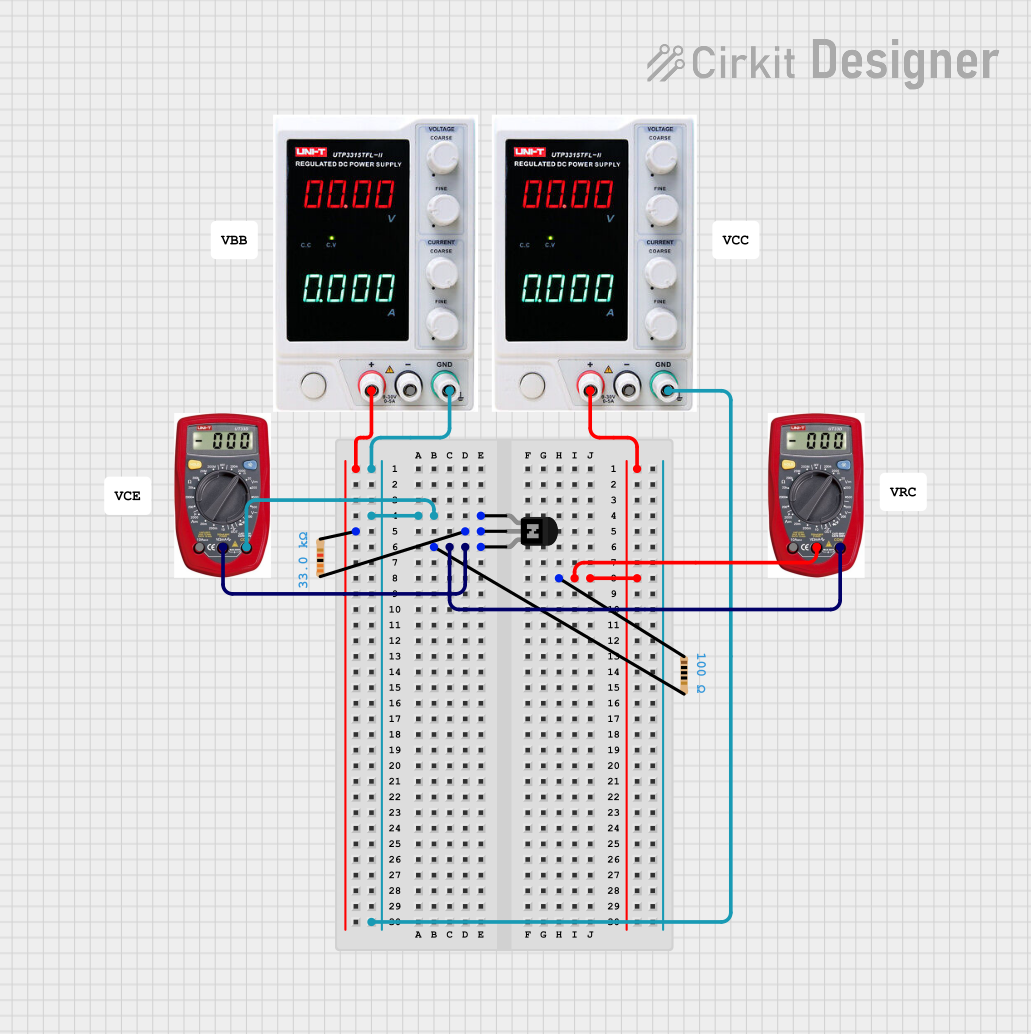
- Test the Circuit: Verify the transistor's operation by measuring the output voltage or current.
Important Considerations and Best Practices
- Heat Dissipation: Ensure proper heat sinking if the transistor is operating at high power levels.
- Voltage Ratings: Do not exceed the maximum collector-emitter voltage (Vce) or collector current (Ic).
- Polarity: Double-check the polarity of the connections to avoid damaging the transistor.
- Signal Amplification: For amplification purposes, ensure the transistor is biased correctly in the active region.
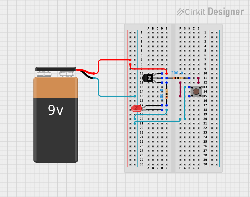
Example: Using the L7805 with an Arduino UNO
Below is an example of using the L7805 transistor as a switch to control an LED with an Arduino UNO:
// Define pin connections
const int transistorBasePin = 9; // Arduino pin connected to the transistor base
const int ledPin = 3;            // LED connected to the transistor's collector

void setup() {
  pinMode(transistorBasePin, OUTPUT); // Set the base pin as an output
  pinMode(ledPin, OUTPUT);            // Set the LED pin as an output
}

void loop() {
  digitalWrite(transistorBasePin, HIGH); // Turn on the transistor (LED ON)
  delay(1000);                           // Wait for 1 second
  digitalWrite(transistorBasePin, LOW);  // Turn off the transistor (LED OFF)
  delay(1000);                           // Wait for 1 second
}
Note: Use a 1kΩ resistor between the Arduino pin and the transistor base to limit the current.
Troubleshooting and FAQs
Common Issues and Solutions
Transistor Not Switching Properly
- Cause: Insufficient base current.
- Solution: Check the base resistor value and ensure the base current is adequate.
Overheating
- Cause: Excessive power dissipation.
- Solution: Use a heat sink or reduce the load current.
No Output Signal
- Cause: Incorrect pin connections.
- Solution: Verify the pinout and ensure proper wiring.
Damaged Transistor
- Cause: Exceeding voltage or current ratings.
- Solution: Replace the transistor and ensure the circuit operates within specified limits.
FAQs
Q1: Can I use the L7805 transistor for high-frequency applications?
A1: The L7805 is not optimized for high-frequency applications. Consider using a transistor specifically designed for RF or high-speed switching.
Q2: How do I test if my transistor is working?
A2: Use a multimeter in diode mode to check the junctions between the base and collector, and the base and emitter. A working transistor will show a forward voltage drop in one direction.
Q3: Can I use the L7805 with a 12V power supply?
A3: Yes, as long as the voltage and current ratings of the transistor are not exceeded.
By following this documentation, you can effectively use the L7805 transistor in your electronic projects.