Cirkit Designer Logo
Cirkit Designer
Your all-in-one circuit design IDE
Home / 
Component Documentation

How to Use Positive Voltage Regulator: Examples, Pinouts, and Specs

Image of Positive Voltage Regulator
Cirkit Designer LogoDesign with Positive Voltage Regulator in Cirkit Designer

Introduction

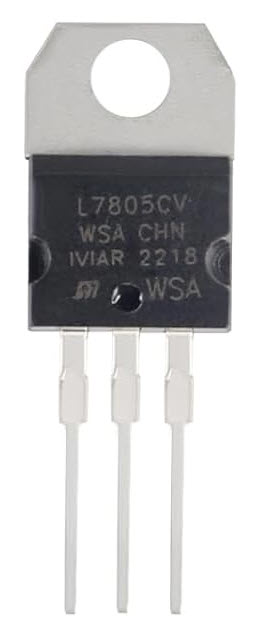
The L7805 Positive Voltage Regulator, manufactured by Professional Semiconductor Suppliers, is a versatile and reliable device designed to maintain a constant output voltage of 5V. It ensures a stable power supply to electronic circuits by regulating fluctuations in input voltage or load conditions. This component is widely used in power supply designs, embedded systems, and various electronic applications requiring a steady 5V output.

Explore Projects Built with Positive Voltage Regulator

Use Cirkit Designer to design, explore, and prototype these projects online. Some projects support real-time simulation. Click "Open Project" to start designing instantly!
Battery-Powered LED Control Circuit with Potentiometer and Transistors
Image of STROBE LIGHTS: A project utilizing Positive Voltage Regulator in a practical application
This circuit is a regulated power supply with a 12V battery input, a 7805 voltage regulator providing a 5V output, and a potentiometer for adjustable voltage control. It includes transistors and resistors for current regulation and an LED indicator to show the operational status.
Cirkit Designer LogoOpen Project in Cirkit Designer
LM317 Voltage Regulator Circuit for Adjustable Power Supply with Transformer and Diodes
Image of 12V BULB LIGHT DIMMER CIRCUIT: A project utilizing Positive Voltage Regulator in a practical application
This circuit is a regulated power supply that converts AC voltage to a stable DC voltage. It uses a transformer to step down the AC voltage, diodes for rectification, an electrolytic capacitor for smoothing, and an LM317 voltage regulator to provide a stable output voltage, which is adjustable via a potentiometer. The output powers a bulb.
Cirkit Designer LogoOpen Project in Cirkit Designer
LD1117 Voltage Regulator Circuit with Input and Output Capacitors
Image of regulator: A project utilizing Positive Voltage Regulator in a practical application
This circuit is designed to provide a stable output voltage from an input voltage source. It uses an LD1117 voltage regulator in conjunction with an electrolytic capacitor on the input side and a tantalum capacitor on the output side to filter noise and stabilize the voltage. The common ground ensures a reference point for all components.
Cirkit Designer LogoOpen Project in Cirkit Designer
12V to 5V Power Supply with LED Indicator and Push Switch
Image of Power Supply LVCO: A project utilizing Positive Voltage Regulator in a practical application
This circuit is a 12V to 5V regulated power supply with an LED indicator. It uses a 5408 diode for reverse polarity protection, an LM340T5 7805 voltage regulator to step down the voltage to 5V, and a push switch to control the LED indicator. The circuit also includes capacitors for filtering and a resistor to limit the current through the LED.
Cirkit Designer LogoOpen Project in Cirkit Designer

Explore Projects Built with Positive Voltage Regulator

Use Cirkit Designer to design, explore, and prototype these projects online. Some projects support real-time simulation. Click "Open Project" to start designing instantly!
Image of STROBE LIGHTS: A project utilizing Positive Voltage Regulator in a practical application
Battery-Powered LED Control Circuit with Potentiometer and Transistors
This circuit is a regulated power supply with a 12V battery input, a 7805 voltage regulator providing a 5V output, and a potentiometer for adjustable voltage control. It includes transistors and resistors for current regulation and an LED indicator to show the operational status.
Cirkit Designer LogoOpen Project in Cirkit Designer
Image of 12V BULB LIGHT DIMMER CIRCUIT: A project utilizing Positive Voltage Regulator in a practical application
LM317 Voltage Regulator Circuit for Adjustable Power Supply with Transformer and Diodes
This circuit is a regulated power supply that converts AC voltage to a stable DC voltage. It uses a transformer to step down the AC voltage, diodes for rectification, an electrolytic capacitor for smoothing, and an LM317 voltage regulator to provide a stable output voltage, which is adjustable via a potentiometer. The output powers a bulb.
Cirkit Designer LogoOpen Project in Cirkit Designer
Image of regulator: A project utilizing Positive Voltage Regulator in a practical application
LD1117 Voltage Regulator Circuit with Input and Output Capacitors
This circuit is designed to provide a stable output voltage from an input voltage source. It uses an LD1117 voltage regulator in conjunction with an electrolytic capacitor on the input side and a tantalum capacitor on the output side to filter noise and stabilize the voltage. The common ground ensures a reference point for all components.
Cirkit Designer LogoOpen Project in Cirkit Designer
Image of Power Supply LVCO: A project utilizing Positive Voltage Regulator in a practical application
12V to 5V Power Supply with LED Indicator and Push Switch
This circuit is a 12V to 5V regulated power supply with an LED indicator. It uses a 5408 diode for reverse polarity protection, an LM340T5 7805 voltage regulator to step down the voltage to 5V, and a push switch to control the LED indicator. The circuit also includes capacitors for filtering and a resistor to limit the current through the LED.
Cirkit Designer LogoOpen Project in Cirkit Designer

Common Applications and Use Cases

  • Power supply for microcontrollers (e.g., Arduino, Raspberry Pi)
  • Voltage regulation in battery-powered devices
  • Stabilizing power for sensors and actuators
  • General-purpose DC voltage regulation in electronic circuits

Technical Specifications

The L7805 is a three-terminal positive voltage regulator with the following key specifications:

Parameter Value
Output Voltage 5V
Input Voltage Range 7V to 35V
Maximum Output Current 1.5A
Dropout Voltage 2V (typical)
Operating Temperature -40°C to +125°C
Package Type TO-220, TO-3, or DPAK
Quiescent Current 6mA (typical)

Pin Configuration and Descriptions

The L7805 has three pins, as shown in the table below:

Pin Number Pin Name Description
1 Input (IN) Connects to the unregulated input voltage source.
2 Ground (GND) Common ground for input and output.
3 Output (OUT) Provides the regulated 5V output voltage.

Usage Instructions

How to Use the L7805 in a Circuit

  1. Input Voltage: Connect a DC voltage source (7V to 35V) to the Input (IN) pin. Ensure the input voltage is at least 2V higher than the desired 5V output for proper regulation.
  2. Output Voltage: Connect the load to the Output (OUT) pin. The regulator will provide a stable 5V output.
  3. Ground Connection: Connect the Ground (GND) pin to the common ground of the circuit.
  4. Capacitors: Add decoupling capacitors to improve stability and reduce noise:
    • A 0.33µF capacitor between the Input (IN) pin and ground.
    • A 0.1µF capacitor between the Output (OUT) pin and ground.

Circuit Diagram

Below is a simple circuit diagram for using the L7805:

   Unregulated Input Voltage
           +7V to +35V
               |
               |
              [C1]  0.33µF
               |
               |-----> IN (Pin 1)
               |            L7805
               |-----> GND (Pin 2)
               |
              [C2]  0.1µF
               |
               |
           Regulated Output Voltage
                  +5V

Arduino UNO Example

The L7805 can be used to power an Arduino UNO by providing a stable 5V supply. Below is an example of how to connect the L7805 to an Arduino UNO:

  1. Connect the Output (OUT) pin of the L7805 to the 5V pin of the Arduino UNO.
  2. Connect the Ground (GND) pin of the L7805 to the GND pin of the Arduino UNO.
  3. Connect the Input (IN) pin of the L7805 to a DC voltage source (e.g., 9V battery or adapter).

Sample Arduino Code

// Example code to blink an LED using Arduino UNO powered by L7805
// Ensure the L7805 provides a stable 5V to the Arduino UNO

const int ledPin = 13; // Built-in LED pin on Arduino UNO

void setup() {
  pinMode(ledPin, OUTPUT); // Set LED pin as output
}

void loop() {
  digitalWrite(ledPin, HIGH); // Turn the LED on
  delay(1000);                // Wait for 1 second
  digitalWrite(ledPin, LOW);  // Turn the LED off
  delay(1000);                // Wait for 1 second
}

Important Considerations and Best Practices

  • Heat Dissipation: The L7805 may generate heat during operation, especially at high input voltages or currents. Use a heatsink if necessary to prevent overheating.
  • Input Voltage: Ensure the input voltage is within the specified range (7V to 35V). Exceeding this range may damage the regulator.
  • Load Current: Do not exceed the maximum output current of 1.5A. Use a current-limiting resistor or fuse if needed.
  • Bypass Capacitors: Always use the recommended capacitors to ensure stable operation and minimize noise.

Troubleshooting and FAQs

Common Issues and Solutions

  1. No Output Voltage

    • Cause: Input voltage is too low.
    • Solution: Ensure the input voltage is at least 7V.
  2. Overheating

    • Cause: Excessive input voltage or current.
    • Solution: Use a heatsink or reduce the input voltage/current.
  3. Output Voltage Fluctuations

    • Cause: Missing or incorrect capacitors.
    • Solution: Add the recommended 0.33µF and 0.1µF capacitors.
  4. Low Output Current

    • Cause: Load exceeds the regulator's capacity.
    • Solution: Ensure the load current is below 1.5A.

FAQs

Q1: Can I use the L7805 to power a 3.3V device?
A1: No, the L7805 provides a fixed 5V output. Use a 3.3V regulator (e.g., LD1117-3.3) for 3.3V devices.

Q2: Can the L7805 regulate AC voltage?
A2: No, the L7805 is designed for DC input only. Use a rectifier and filter circuit to convert AC to DC before using the L7805.

Q3: What happens if I connect the input voltage in reverse?
A3: Reversing the input voltage can damage the regulator. Use a diode in series with the input to prevent reverse polarity.

Q4: Can I use the L7805 without capacitors?
A4: While the L7805 may work without capacitors, it is not recommended. Capacitors improve stability and reduce noise.

By following this documentation, you can effectively use the L7805 Positive Voltage Regulator in your electronic projects.