How to Use TFT 1.28 ROUND DISPLAY: Examples, Pinouts, and Specs
Introduction
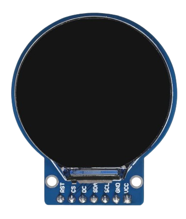
The TFT 1.28 ROUND DISPLAY is a 1.28-inch round thin-film transistor (TFT) display designed to deliver high-resolution color output. Its compact size and vibrant display make it an excellent choice for applications requiring a small, visually appealing interface. Common use cases include smartwatches, fitness trackers, medical devices, and other compact electronic gadgets. The display's round form factor and high pixel density provide a modern and sleek aesthetic for user interfaces.
Explore Projects Built with TFT 1.28 ROUND DISPLAY


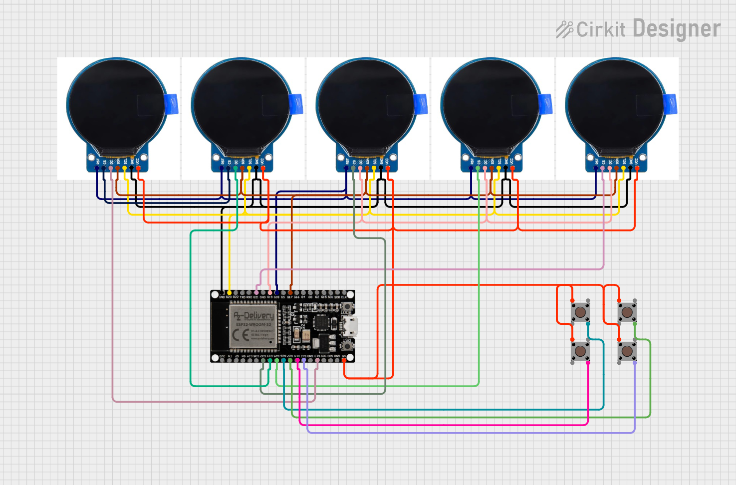

Explore Projects Built with TFT 1.28 ROUND DISPLAY
Technical Specifications
Below are the key technical details and pin configuration for the TFT 1.28 ROUND DISPLAY:
Key Technical Details
| Parameter | Value |
|---|---|
| Display Type | TFT (Thin-Film Transistor) |
| Screen Size | 1.28 inches (round) |
| Resolution | 240 x 240 pixels |
| Interface | SPI (Serial Peripheral Interface) |
| Operating Voltage | 3.3V |
| Backlight Voltage | 3.0V - 3.3V |
| Current Consumption | ~20mA (typical) |
| Viewing Angle | 160° |
| Operating Temperature | -20°C to 70°C |
| Driver IC | GC9A01 |
Pin Configuration and Descriptions
| Pin Name | Pin Number | Description |
|---|---|---|
| VCC | 1 | Power supply input (3.3V). |
| GND | 2 | Ground connection. |
| SCL | 3 | SPI clock line (SCK). |
| SDA | 4 | SPI data line (MOSI). |
| RES | 5 | Reset pin (active low). |
| DC | 6 | Data/Command control pin. |
| CS | 7 | Chip select pin (active low). |
| BLK | 8 | Backlight control pin (PWM or ON/OFF). |
Usage Instructions
How to Use the Component in a Circuit
- Power Supply: Connect the VCC pin to a 3.3V power source and the GND pin to ground.
- SPI Communication: Connect the SCL (SPI clock) and SDA (SPI data) pins to the corresponding SPI pins on your microcontroller.
- Control Pins:
- Connect the RES pin to a GPIO pin on your microcontroller for resetting the display.
- Use the DC pin to toggle between data and command modes.
- Connect the CS pin to a GPIO pin to enable or disable the display.
- Backlight: The BLK pin can be connected to a PWM-capable GPIO pin for brightness control or directly to 3.3V for constant backlight.
Important Considerations and Best Practices
- Voltage Levels: Ensure all input signals are 3.3V logic level. Use level shifters if your microcontroller operates at 5V.
- Capacitors: Add decoupling capacitors (e.g., 0.1µF) near the VCC and GND pins to stabilize the power supply.
- Reset Sequence: Always perform a reset sequence during initialization to ensure proper operation.
- SPI Speed: Use an SPI clock speed of up to 10MHz for optimal performance.
Example Code for Arduino UNO
Below is an example of how to interface the TFT 1.28 ROUND DISPLAY with an Arduino UNO using the Adafruit_GFX and Adafruit_GC9A01 libraries:
#include <Adafruit_GFX.h>       // Core graphics library
#include <Adafruit_GC9A01.h>    // Driver for GC9A01 display

// Define pin connections
#define TFT_CS   10  // Chip select pin
#define TFT_DC    9  // Data/Command pin
#define TFT_RST   8  // Reset pin

// Initialize the display object
Adafruit_GC9A01 tft = Adafruit_GC9A01(TFT_CS, TFT_DC, TFT_RST);

void setup() {
  // Initialize serial communication for debugging
  Serial.begin(9600);
  Serial.println("TFT 1.28 ROUND DISPLAY Test");

  // Initialize the display
  tft.begin();
  tft.setRotation(0);  // Set display rotation (0-3)
  tft.fillScreen(0x0000);  // Clear screen with black color

  // Draw a test pattern
  tft.setTextColor(0xFFFF);  // Set text color to white
  tft.setTextSize(2);        // Set text size
  tft.setCursor(20, 60);     // Set cursor position
  tft.println("Hello, TFT!"); // Print text on the display
}

void loop() {
  // Add your code here for dynamic updates
}
Notes:
- Install the Adafruit_GFX and Adafruit_GC9A01 libraries via the Arduino Library Manager before running the code.
- Adjust the pin definitions if using a different microcontroller.
Troubleshooting and FAQs
Common Issues and Solutions
Display Not Turning On:
- Verify the power supply voltage (3.3V) and connections to the VCC and GND pins.
- Check the backlight (BLK) pin connection.
No Output on the Screen:
- Ensure the SPI connections (SCL, SDA) are correctly wired to the microcontroller.
- Confirm that the CS, DC, and RES pins are properly configured in the code.
Flickering or Unstable Display:
- Use decoupling capacitors near the power pins to reduce noise.
- Lower the SPI clock speed if the issue persists.
Partial or Distorted Graphics:
- Verify the initialization sequence in the code matches the display's requirements.
- Ensure the correct driver (GC9A01) is being used in the software.
FAQs
Q: Can I use this display with a 5V microcontroller?
A: Yes, but you must use level shifters to convert 5V logic signals to 3.3V.
Q: What is the maximum SPI clock speed supported?
A: The display supports SPI clock speeds up to 10MHz.
Q: Can I control the backlight brightness?
A: Yes, connect the BLK pin to a PWM-capable GPIO pin for brightness control.
Q: Is this display compatible with Raspberry Pi?
A: Yes, the display can be used with Raspberry Pi via SPI, but you may need to modify the software configuration.
This concludes the documentation for the TFT 1.28 ROUND DISPLAY.