How to Use max3421E: Examples, Pinouts, and Specs
Introduction
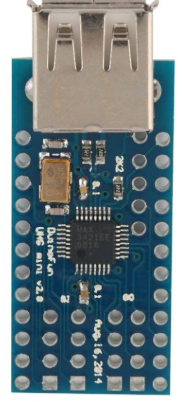
The MAX3421E is a USB peripheral controller that enables microcontrollers to communicate with USB devices. It features a full-speed USB interface and supports various USB protocols, including control, bulk, interrupt, and isochronous transfers. This component is widely used in applications requiring USB connectivity, such as embedded systems, USB host controllers, and USB device emulation.
Explore Projects Built with max3421E
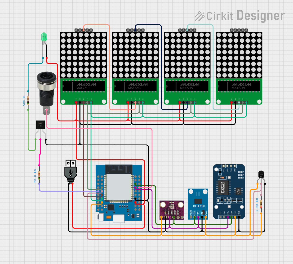
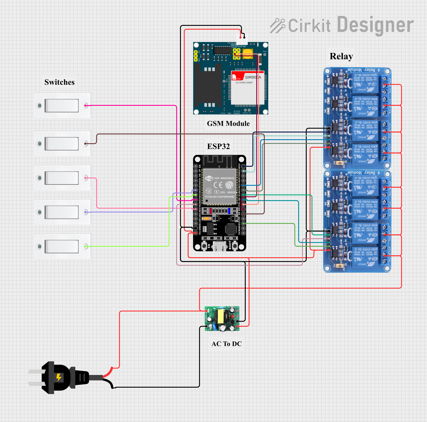


Explore Projects Built with max3421E
Common Applications and Use Cases
- USB host controllers for microcontrollers
- USB device emulation
- Embedded systems requiring USB communication
- USB data logging and debugging tools
- USB-to-serial converters
Technical Specifications
Key Technical Details
- USB Interface: Full-speed (12 Mbps)
- Operating Voltage: 3.3V (core), 5V tolerant I/O
- Current Consumption: 15 mA (typical)
- Communication Interface: SPI (Serial Peripheral Interface)
- Clock Frequency: Up to 26 MHz
- Package Options: 24-pin TQFN, 32-pin TQFP
- Temperature Range: -40°C to +85°C (industrial grade)
Pin Configuration and Descriptions
The MAX3421E is available in multiple package types. Below is the pin configuration for the 24-pin TQFN package:
| Pin Number | Pin Name | Description |
|---|---|---|
| 1 | VCC | 3.3V power supply input. |
| 2 | GND | Ground connection. |
| 3 | MOSI | SPI Master Out Slave In (data input to MAX3421E). |
| 4 | MISO | SPI Master In Slave Out (data output from MAX3421E). |
| 5 | SCK | SPI clock input. |
| 6 | SS | SPI slave select input (active low). |
| 7 | INT | Interrupt output (active low). |
| 8 | RESET | Active-low reset input. |
| 9 | GPX | General-purpose output or interrupt pin. |
| 10 | VBUS | USB bus power detection input. |
| 11 | D+ | USB data line (positive). |
| 12 | D- | USB data line (negative). |
| 13-24 | NC | No connection (reserved for future use). |
Usage Instructions
How to Use the MAX3421E in a Circuit
- Power Supply: Connect the VCC pin to a 3.3V power source and GND to ground. Ensure proper decoupling capacitors (e.g., 0.1 µF) are placed close to the VCC pin.
- SPI Communication: Connect the SPI pins (MOSI, MISO, SCK, and SS) to the corresponding SPI pins on your microcontroller. Configure the SPI interface to operate in Mode 0 (CPOL=0, CPHA=0).
- USB Connection: Connect the D+ and D- pins to the USB device. Use a 1.5 kΩ pull-up resistor on the D+ line to indicate a full-speed USB device.
- Interrupt Handling: Connect the INT pin to a GPIO pin on the microcontroller to handle USB events.
- Reset: Use the RESET pin to initialize the MAX3421E during power-up or when required.
Important Considerations and Best Practices
- Use proper decoupling capacitors to minimize noise and ensure stable operation.
- Ensure the SPI clock frequency does not exceed 26 MHz.
- Handle USB interrupts promptly to avoid data loss or communication errors.
- Use a level shifter if interfacing with a 5V microcontroller, as the MAX3421E operates at 3.3V.
Example: Interfacing MAX3421E with Arduino UNO
Below is an example of how to interface the MAX3421E with an Arduino UNO to act as a USB host:
Circuit Connections
- VCC: Connect to the 3.3V pin on the Arduino.
- GND: Connect to the GND pin on the Arduino.
- MOSI: Connect to pin 11 on the Arduino.
- MISO: Connect to pin 12 on the Arduino.
- SCK: Connect to pin 13 on the Arduino.
- SS: Connect to pin 10 on the Arduino.
- INT: Connect to pin 2 on the Arduino.
- RESET: Connect to pin 9 on the Arduino.
Arduino Code Example
#include <SPI.h>
#include <USBHost.h> // Include USB Host library for MAX3421E

USBHost usb; // Create USBHost object

void setup() {
  Serial.begin(9600); // Initialize serial communication
  while (!Serial) {
    ; // Wait for serial port to connect
  }

  Serial.println("Initializing USB Host...");
  if (usb.begin()) {
    Serial.println("USB Host initialized successfully.");
  } else {
    Serial.println("Failed to initialize USB Host.");
  }
}

void loop() {
  usb.Task(); // Process USB events

  // Add your USB device handling code here
  // For example, detecting a connected USB device
  if (usb.getDeviceCount() > 0) {
    Serial.println("USB device connected.");
  } else {
    Serial.println("No USB device connected.");
  }

  delay(1000); // Wait for 1 second
}
Troubleshooting and FAQs
Common Issues and Solutions
No USB Device Detected
- Cause: Incorrect wiring or missing pull-up resistor on the D+ line.
- Solution: Verify all connections and ensure a 1.5 kΩ pull-up resistor is connected to the D+ line.
SPI Communication Fails
- Cause: Incorrect SPI mode or clock frequency.
- Solution: Ensure the SPI interface is configured for Mode 0 and the clock frequency is within the MAX3421E's specifications.
Interrupts Not Triggering
- Cause: INT pin not connected or microcontroller not configured to handle interrupts.
- Solution: Verify the INT pin connection and configure the microcontroller to handle external interrupts.
Device Not Recognized by USB Host
- Cause: Improper USB initialization or unsupported device.
- Solution: Check the USB initialization code and ensure the connected device is supported.
FAQs
Q: Can the MAX3421E operate as a USB device?
A: No, the MAX3421E is designed to function as a USB host controller.Q: What is the maximum SPI clock frequency supported?
A: The MAX3421E supports SPI clock frequencies up to 26 MHz.Q: Is the MAX3421E compatible with 5V microcontrollers?
A: Yes, the I/O pins are 5V tolerant, but the core operates at 3.3V. Use level shifters if needed.Q: Can I use the MAX3421E with other microcontrollers besides Arduino?
A: Yes, the MAX3421E can be used with any microcontroller that supports SPI communication.