How to Use Adafruit Thermocouple Amplifier MAX31855: Examples, Pinouts, and Specs
Introduction
The Adafruit Thermocouple Amplifier MAX31855 is a sophisticated electronic component designed to interface with thermocouple sensors, specifically Type-K thermocouples. It amplifies the small voltage from the thermocouple and converts it to a digital value, allowing for accurate temperature readings. This module communicates with microcontrollers such as Arduino via the Serial Peripheral Interface (SPI) protocol. It is commonly used in applications requiring precise temperature monitoring, such as industrial equipment, consumer appliances, and scientific instrumentation.
Explore Projects Built with Adafruit Thermocouple Amplifier MAX31855

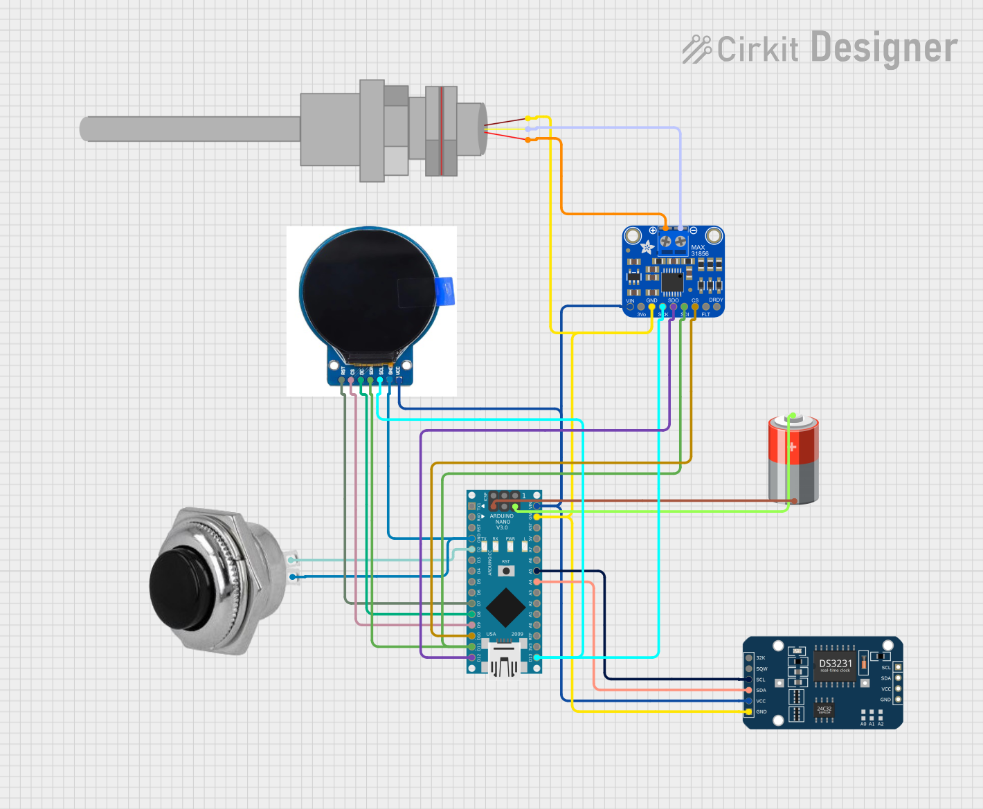
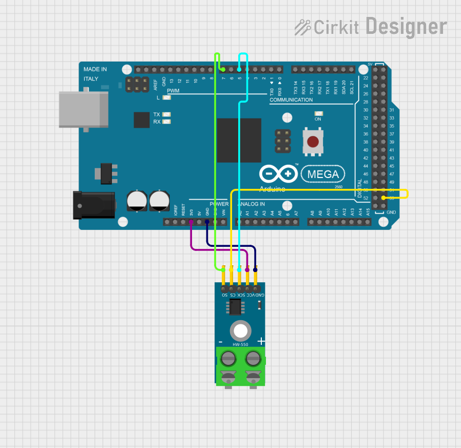
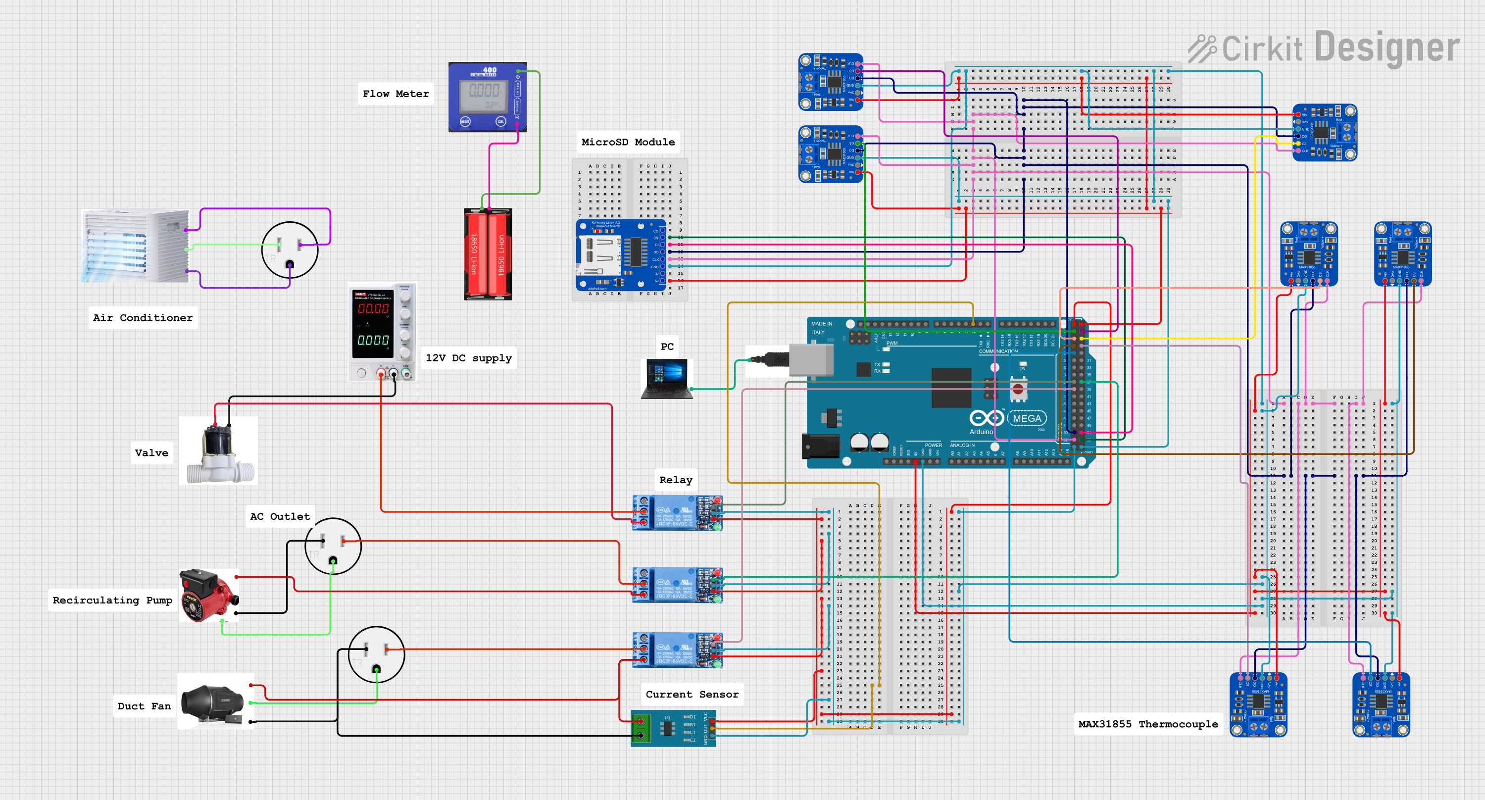
Explore Projects Built with Adafruit Thermocouple Amplifier MAX31855
Technical Specifications
Key Technical Details
- Supply Voltage: 3.0 to 3.6V
- Operating Current: 1.5mA
- Temperature Resolution: 0.25°C
- Temperature Range (Type-K): -200°C to +1350°C (dependent on thermocouple type)
- Interface: SPI
- Accuracy: ±2°C (typical)
- Thermocouple Input: Differential Input Voltage: ±210mV
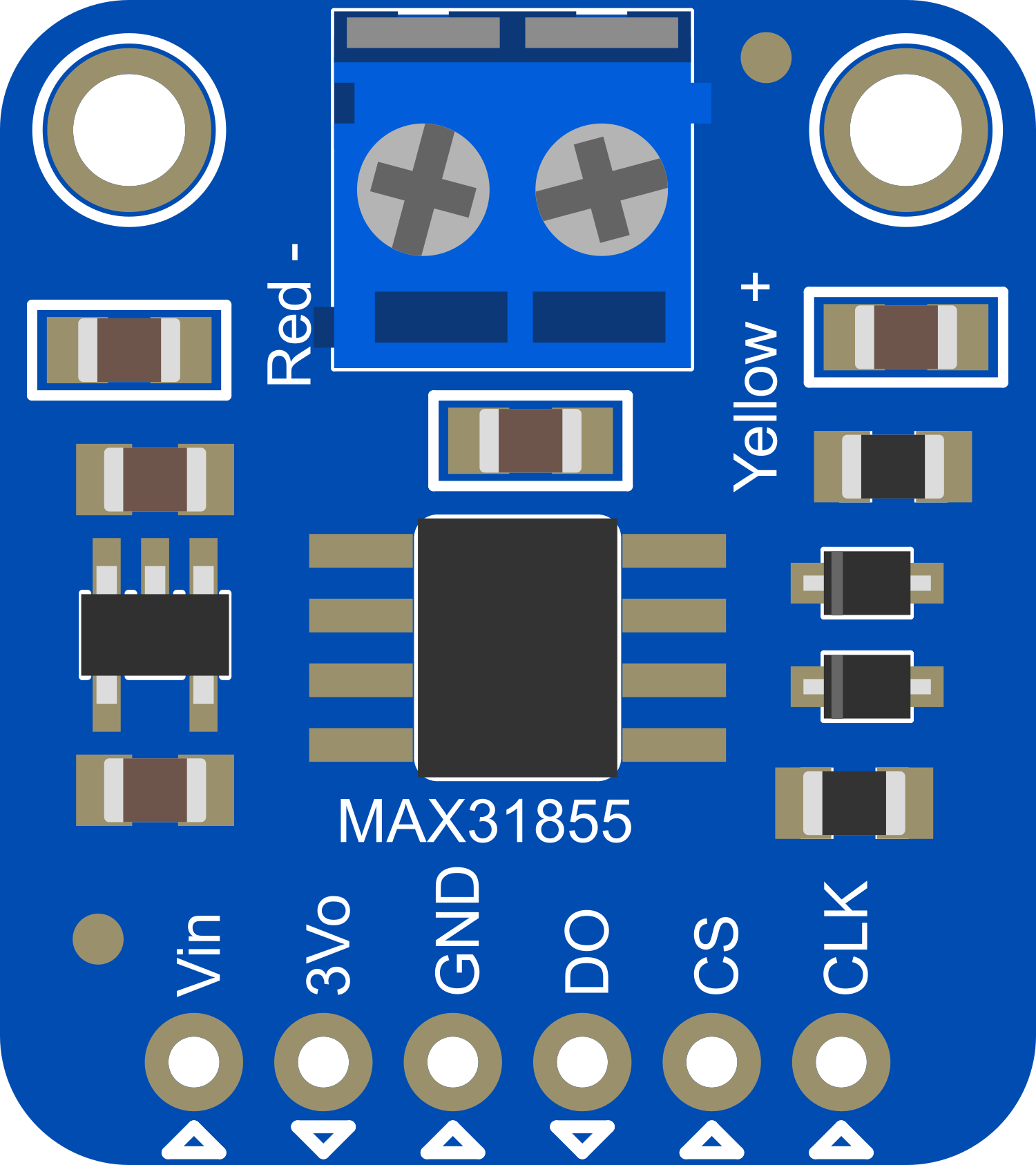
Pin Configuration and Descriptions
| Pin Number | Name | Description |
|---|---|---|
| 1 | VDD | Power supply (3.0 to 3.6V) |
| 2 | GND | Ground |
| 3 | DO | Data Output for SPI interface |
| 4 | CS | Chip Select for SPI interface |
| 5 | CLK | Clock Input for SPI interface |
| 6 | NC | No Connection (leave unconnected) |
| 7 | VIN+ | Positive Thermocouple Input |
| 8 | VIN- | Negative Thermocouple Input |
Usage Instructions
Connecting to a Circuit
- Power Connections: Connect VDD to a 3.3V supply and GND to the ground.
- SPI Connections: Connect DO, CS, and CLK to the corresponding SPI pins on your microcontroller.
- Thermocouple Connections: Connect the positive and negative leads of your Type-K thermocouple to VIN+ and VIN-, respectively.
Important Considerations and Best Practices
- Ensure that the power supply is within the specified range (3.0 to 3.6V).
- Use short, twisted-pair wires for the thermocouple to minimize noise and thermal EMF errors.
- Avoid placing the module near heat sources or areas with rapid temperature changes to prevent false readings.
- Use proper ESD precautions when handling the module to prevent damage to the sensitive circuitry.
Example Arduino Code
#include <SPI.h>
#include <Adafruit_MAX31855.h>

// Define the pins used for the SPI connection
int thermoDO = 4;
int thermoCS = 5;
int thermoCLK = 6;

// Initialize the MAX31855 library with the pins
Adafruit_MAX31855 thermocouple(thermoCLK, thermoCS, thermoDO);

void setup() {
  Serial.begin(9600);
  // Ensure the thermocouple is connected properly
  if (!thermocouple.begin()) {
    Serial.println("Error: No thermocouple connected!");
    while (1) delay(500);
  }
}

void loop() {
  // Read the temperature in Celsius
  double temperature = thermocouple.readCelsius();
  if (isnan(temperature)) {
    Serial.println("Error: Could not read temperature data!");
  } else {
    Serial.print("Temperature: ");
    Serial.print(temperature);
    Serial.println(" C");
  }
  delay(1000);
}
Troubleshooting and FAQs
Common Issues
- No Temperature Data: Ensure that the thermocouple is properly connected to VIN+ and VIN- and that the SPI connections are secure.
- Inaccurate Readings: Check for sources of electromagnetic interference or rapid temperature changes near the sensor. Also, verify that the thermocouple is a Type-K and is not damaged.
- SPI Communication Errors: Confirm that the SPI pins are correctly connected and that the correct SPI mode is set in your microcontroller's code.
FAQs
Q: Can I use a different type of thermocouple with this module? A: The MAX31855 is specifically designed for use with Type-K thermocouples. Using other types may result in inaccurate readings or no readings at all.
Q: How can I extend the distance between the thermocouple and the module? A: Use thermocouple extension wire, which is made of the same material as the thermocouple, to minimize errors. Keep the extension as short as possible and away from sources of electrical noise.
Q: What is the maximum frequency of temperature readings? A: The MAX31855 performs a temperature conversion every 100ms, so the maximum theoretical frequency is 10 readings per second. However, in practice, the frequency will be lower due to communication overhead and processing time.
Q: Is calibration required for this module? A: The MAX31855 is factory-calibrated for Type-K thermocouples. However, for critical applications, additional calibration against a known temperature standard may be necessary.
For further assistance, consult the Adafruit MAX31855 datasheet and the Adafruit support forums.