
How to Use TB6612FNG motor driver: Examples, Pinouts, and Specs
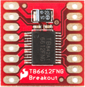
 Design with TB6612FNG motor driver in Cirkit Designer
Introduction
The TB6612FNG is a dual H-bridge motor driver IC designed for controlling two DC motors or one stepper motor. It supports PWM (Pulse Width Modulation) for precise speed control and direction management. The IC is compact, efficient, and includes built-in protection features such as overcurrent and thermal shutdown, making it ideal for a wide range of motor control applications.
Explore Projects Built with TB6612FNG motor driver
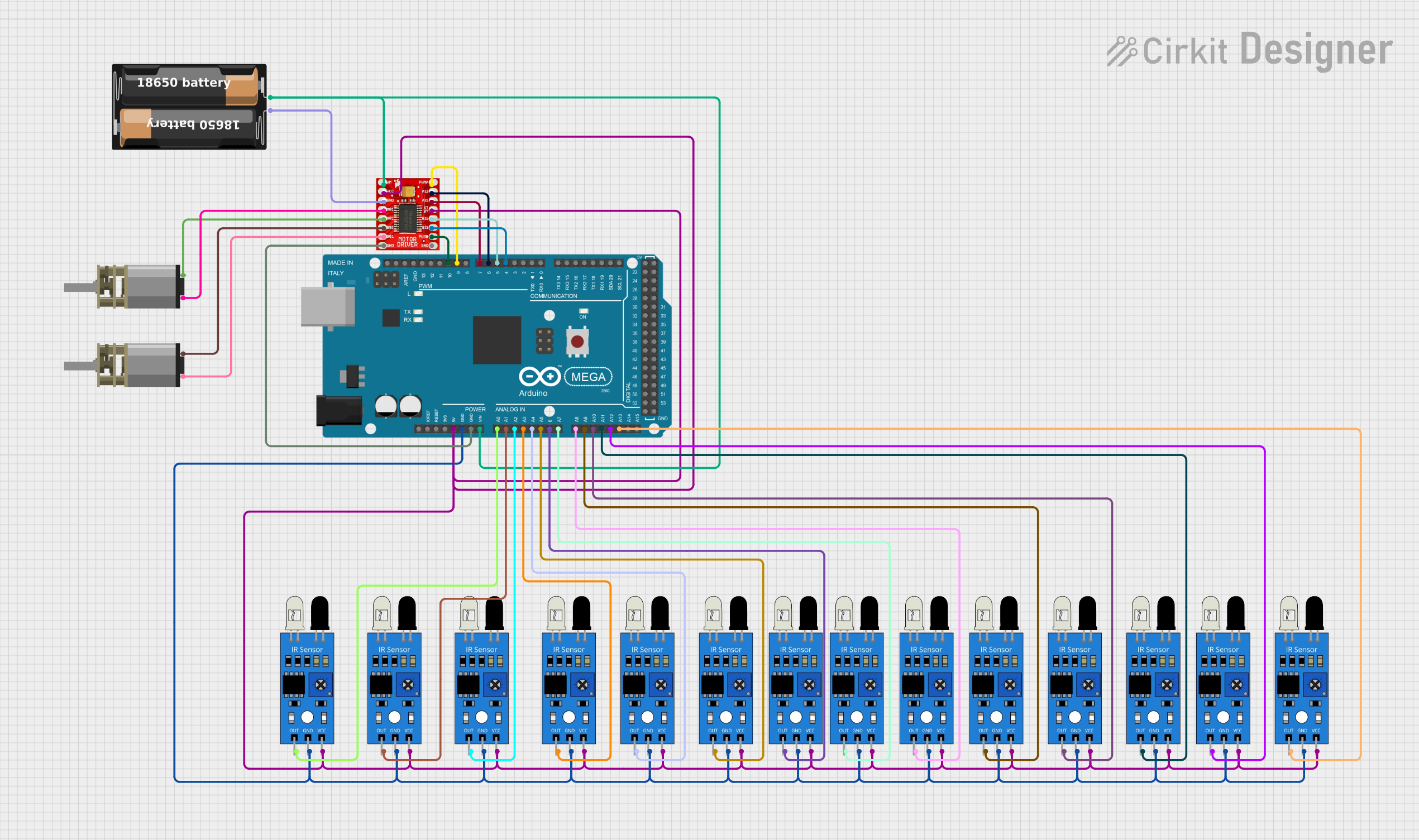 Open Project in Cirkit Designer
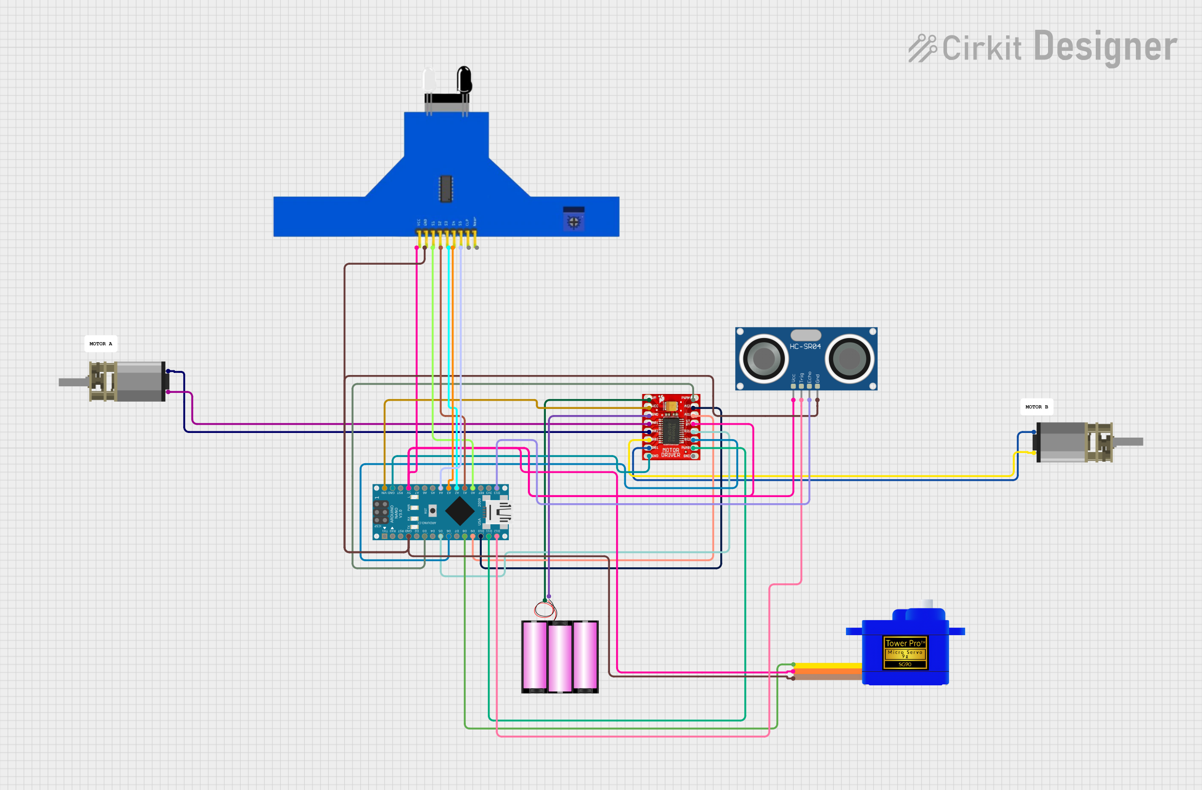 Open Project in Cirkit Designer
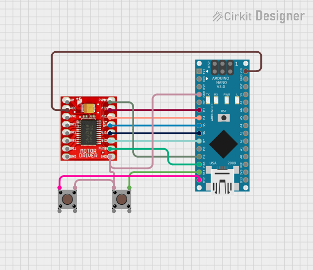 Open Project in Cirkit Designer
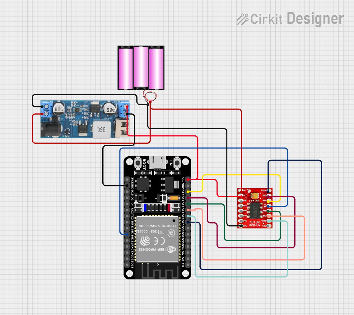 Open Project in Cirkit Designer
Explore Projects Built with TB6612FNG motor driver
Open Project in Cirkit DesignerOpen Project in Cirkit DesignerOpen Project in Cirkit DesignerOpen Project in Cirkit DesignerCommon Applications and Use Cases
- Robotics and automation systems
- Remote-controlled vehicles
- Conveyor belts and industrial machinery
- DIY electronics and hobbyist projects
- Stepper motor control for 3D printers and CNC machines
Technical Specifications
Key Technical Details
- Operating Voltage (Vcc): 2.7V to 5.5V
- Motor Voltage (VM): 4.5V to 13.5V
- Output Current (per channel): 1.2A (continuous), 3.2A (peak)
- Control Inputs: PWM, IN1, IN2 for each motor
- Standby Current: 1 µA (typical)
- Built-in Protections: Overcurrent, thermal shutdown, and undervoltage lockout
- Operating Temperature Range: -20°C to +85°C
- Package Type: HTSSOP-20
Pin Configuration and Descriptions
The TB6612FNG has 20 pins. Below is the pinout and description:
| Pin Number | Pin Name | Description |
|---|---|---|
| 1 | VCC | Logic power supply (2.7V to 5.5V). |
| 2 | GND | Ground connection. |
| 3 | AIN1 | Input 1 for Motor A. Controls direction when combined with AIN2. |
| 4 | AIN2 | Input 2 for Motor A. Controls direction when combined with AIN1. |
| 5 | PWMA | PWM input for Motor A. Controls speed. |
| 6 | A01 | Output 1 for Motor A. Connect to one terminal of Motor A. |
| 7 | A02 | Output 2 for Motor A. Connect to the other terminal of Motor A. |
| 8 | VM | Motor power supply (4.5V to 13.5V). |
| 9 | STBY | Standby control. Pull HIGH to enable the IC, LOW to disable. |
| 10 | BIN1 | Input 1 for Motor B. Controls direction when combined with BIN2. |
| 11 | BIN2 | Input 2 for Motor B. Controls direction when combined with BIN1. |
| 12 | PWMB | PWM input for Motor B. Controls speed. |
| 13 | B01 | Output 1 for Motor B. Connect to one terminal of Motor B. |
| 14 | B02 | Output 2 for Motor B. Connect to the other terminal of Motor B. |
| 15 | NC | No connection. |
| 16 | NC | No connection. |
| 17 | NC | No connection. |
| 18 | NC | No connection. |
| 19 | NC | No connection. |
| 20 | NC | No connection. |
Usage Instructions
How to Use the TB6612FNG in a Circuit
Power Connections:
- Connect the logic power supply (2.7V to 5.5V) to the VCC pin.
- Connect the motor power supply (4.5V to 13.5V) to the VM pin.
- Connect the GND pin to the ground of the circuit.
Motor Connections:
- For Motor A, connect its terminals to A01 and A02.
- For Motor B, connect its terminals to B01 and B02.
Control Inputs:
- Use AIN1 and AIN2 to control the direction of Motor A.
- Use BIN1 and BIN2 to control the direction of Motor B.
- Apply PWM signals to PWMA and PWMB to control the speed of Motor A and Motor B, respectively.
Standby Mode:
- Pull the STBY pin HIGH to enable the IC.
- Pull the STBY pin LOW to disable the IC and reduce power consumption.
Important Considerations and Best Practices
- Ensure that the motor power supply (VM) matches the voltage requirements of your motors.
- Use appropriate decoupling capacitors (e.g., 0.1 µF and 10 µF) near the VCC and VM pins to stabilize the power supply.
- Avoid exceeding the maximum current ratings to prevent damage to the IC.
- Use heatsinks or proper ventilation if operating near the maximum current limits for extended periods.
Example Code for Arduino UNO
Below is an example of how to control two DC motors using the TB6612FNG with an Arduino UNO:
// Define motor control pins
#define AIN1 7  // Motor A direction pin 1
#define AIN2 8  // Motor A direction pin 2
#define PWMA 9  // Motor A speed (PWM) pin
#define BIN1 10 // Motor B direction pin 1
#define BIN2 11 // Motor B direction pin 2
#define PWMB 3  // Motor B speed (PWM) pin
#define STBY 4  // Standby pin

void setup() {
  // Set motor control pins as outputs
  pinMode(AIN1, OUTPUT);
  pinMode(AIN2, OUTPUT);
  pinMode(PWMA, OUTPUT);
  pinMode(BIN1, OUTPUT);
  pinMode(BIN2, OUTPUT);
  pinMode(PWMB, OUTPUT);
  pinMode(STBY, OUTPUT);

  // Enable the motor driver by pulling STBY HIGH
  digitalWrite(STBY, HIGH);
}

void loop() {
  // Example: Run Motor A forward at 50% speed
  digitalWrite(AIN1, HIGH); // Set direction
  digitalWrite(AIN2, LOW);
  analogWrite(PWMA, 128);   // Set speed (0-255)

  // Example: Run Motor B backward at 75% speed
  digitalWrite(BIN1, LOW);  // Set direction
  digitalWrite(BIN2, HIGH);
  analogWrite(PWMB, 192);   // Set speed (0-255)

  delay(2000); // Run motors for 2 seconds

  // Stop both motors
  analogWrite(PWMA, 0);
  analogWrite(PWMB, 0);

  delay(2000); // Wait for 2 seconds
}
Troubleshooting and FAQs
Common Issues and Solutions
Motors Not Running:
- Ensure the STBY pin is pulled HIGH to enable the IC.
- Verify that the motor power supply (VM) is connected and within the specified range.
- Check the PWM signal and ensure it is being generated correctly.
Overheating:
- Ensure the current drawn by the motors does not exceed the IC's maximum ratings.
- Use proper cooling methods, such as heatsinks or fans, if necessary.
Erratic Motor Behavior:
- Check for loose or incorrect wiring connections.
- Add decoupling capacitors near the power supply pins to reduce noise.
Arduino Code Not Working:
- Verify that the pin numbers in the code match your circuit connections.
- Ensure the Arduino is powered and properly connected to the motor driver.
FAQs
Q: Can the TB6612FNG drive stepper motors?
A: Yes, the TB6612FNG can drive a single stepper motor by controlling its coils using the two H-bridges.
Q: What happens if the IC overheats?
A: The TB6612FNG has a built-in thermal shutdown feature that disables the outputs to protect the IC from damage.
Q: Can I use the TB6612FNG with a 3.3V microcontroller?
A: Yes, the TB6612FNG supports logic levels as low as 2.7V, making it compatible with 3.3V microcontrollers.