How to Use Convertidor Voltaje DC-DC : Examples, Pinouts, and Specs
Introduction
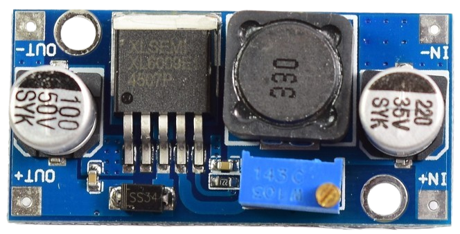
The Convertidor Voltaje DC-DC (Manufacturer Part ID: ONU), manufactured by Arduino, is an electronic device designed to efficiently convert direct current (DC) from one voltage level to another. This component is essential for power management in a wide range of applications, enabling devices to operate at their required voltage levels while minimizing energy loss.
Explore Projects Built with Convertidor Voltaje DC-DC


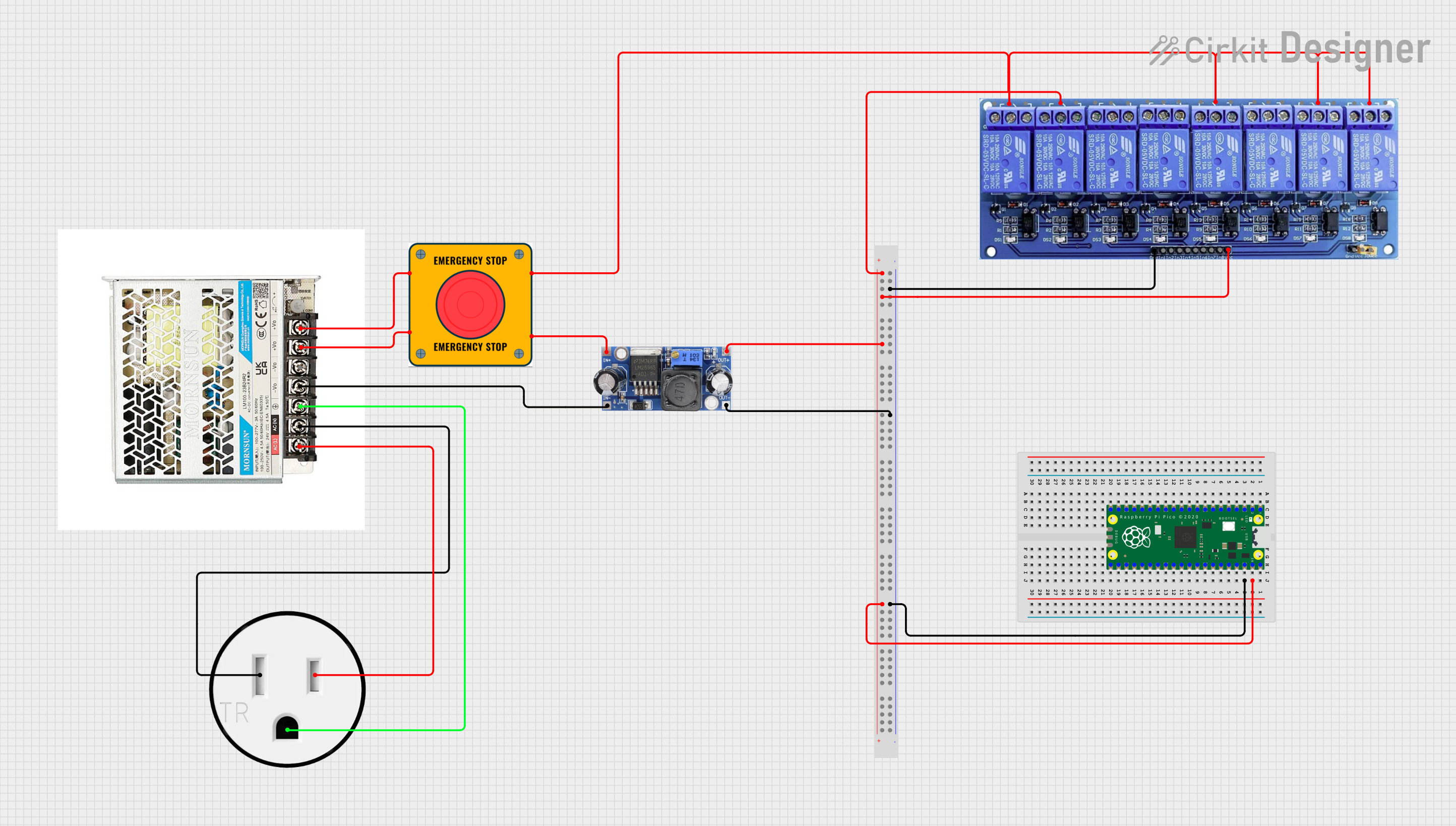
Explore Projects Built with Convertidor Voltaje DC-DC
Common Applications and Use Cases
- Powering microcontrollers and sensors from a higher voltage source
- Battery-powered devices requiring voltage step-up or step-down
- Renewable energy systems, such as solar panels
- Automotive electronics for voltage regulation
- Portable electronics and USB-powered devices
Technical Specifications
The following table outlines the key technical details of the Convertidor Voltaje DC-DC:
| Parameter | Value |
|---|---|
| Input Voltage Range | 3.3V to 40V |
| Output Voltage Range | 1.25V to 35V |
| Maximum Output Current | 3A (with proper heat dissipation) |
| Efficiency | Up to 92% |
| Switching Frequency | 150 kHz |
| Operating Temperature | -40°C to +85°C |
| Dimensions | 43mm x 21mm x 14mm |
Pin Configuration and Descriptions
The Convertidor Voltaje DC-DC has the following pin configuration:
| Pin Name | Description |
|---|---|
| VIN | Input voltage pin. Connect the DC power source to this pin. |
| GND | Ground pin. Connect to the ground of the circuit. |
| VOUT | Output voltage pin. Provides the regulated DC voltage to the load. |
| ADJ | Adjustment pin. Used to set the output voltage by connecting an external resistor. |
Usage Instructions
How to Use the Component in a Circuit
Connect the Input Voltage (VIN):
Attach the DC power source to the VIN pin. Ensure the input voltage is within the specified range (3.3V to 40V).Connect the Ground (GND):
Connect the GND pin to the ground of your circuit.Set the Output Voltage (VOUT):
- Use the ADJ pin to set the desired output voltage. This is typically done by adjusting a potentiometer or using an external resistor.
- Measure the output voltage using a multimeter to ensure it matches your requirements.
Connect the Load:
Attach the device or circuit requiring the regulated voltage to the VOUT pin.Verify Connections:
Double-check all connections before powering the circuit to avoid damage to the component or connected devices.
Important Considerations and Best Practices
Heat Dissipation:
If the output current exceeds 2A, ensure proper heat dissipation by attaching a heatsink to the component.Input Voltage:
Always ensure the input voltage is higher than the desired output voltage for step-down operation. For step-up operation, ensure the input voltage is within the supported range.Capacitors:
Add input and output capacitors (e.g., 10µF to 100µF) to stabilize the voltage and reduce noise.Polarity:
Ensure correct polarity when connecting the input and output terminals to avoid damage.
Example: Using with Arduino UNO
The Convertidor Voltaje DC-DC can be used to power an Arduino UNO from a higher voltage source. Below is an example setup:
- Connect a 12V DC power source to the VIN pin of the converter.
- Adjust the output voltage to 5V using the ADJ pin.
- Connect the VOUT pin to the 5V pin of the Arduino UNO.
- Connect the GND pin of the converter to the GND pin of the Arduino UNO.
Here is an example Arduino code to test the setup with an LED:
// This code blinks an LED connected to pin 13 of the Arduino UNO.
// Ensure the DC-DC converter is providing 5V to the Arduino UNO.

void setup() {
  pinMode(13, OUTPUT); // Set pin 13 as an output pin
}

void loop() {
  digitalWrite(13, HIGH); // Turn the LED on
  delay(1000);            // Wait for 1 second
  digitalWrite(13, LOW);  // Turn the LED off
  delay(1000);            // Wait for 1 second
}
Troubleshooting and FAQs
Common Issues Users Might Face
No Output Voltage:
- Cause: Incorrect input voltage or loose connections.
- Solution: Verify the input voltage is within the specified range and check all connections.
Overheating:
- Cause: High output current without proper heat dissipation.
- Solution: Attach a heatsink to the component and ensure adequate ventilation.
Unstable Output Voltage:
- Cause: Insufficient input/output capacitors or incorrect adjustment of the ADJ pin.
- Solution: Add capacitors (10µF to 100µF) to the input and output terminals. Recheck the ADJ pin settings.
Component Damage:
- Cause: Reversed polarity or exceeding voltage/current limits.
- Solution: Always double-check polarity and ensure the input/output parameters are within the specified range.
FAQs
Q: Can this converter step up and step down voltage?
A: No, this is a step-down (buck) converter. The input voltage must always be higher than the desired output voltage.
Q: What is the maximum current this converter can handle?
A: The converter can handle up to 3A with proper heat dissipation. Without a heatsink, it is recommended to limit the current to 2A.
Q: Can I use this converter with a battery?
A: Yes, the converter can be used with batteries as long as the input voltage is within the specified range (3.3V to 40V).
Q: How do I adjust the output voltage?
A: Use the ADJ pin to set the output voltage. This is typically done by turning a potentiometer or connecting an external resistor.
By following this documentation, users can effectively integrate the Convertidor Voltaje DC-DC into their projects for efficient power management.