Cirkit Designer Logo
Cirkit Designer
Your all-in-one circuit design IDE
Home / 
Component Documentation

How to Use RelayModuleI2C: Examples, Pinouts, and Specs

Image of RelayModuleI2C
Cirkit Designer LogoDesign with RelayModuleI2C in Cirkit Designer

Introduction

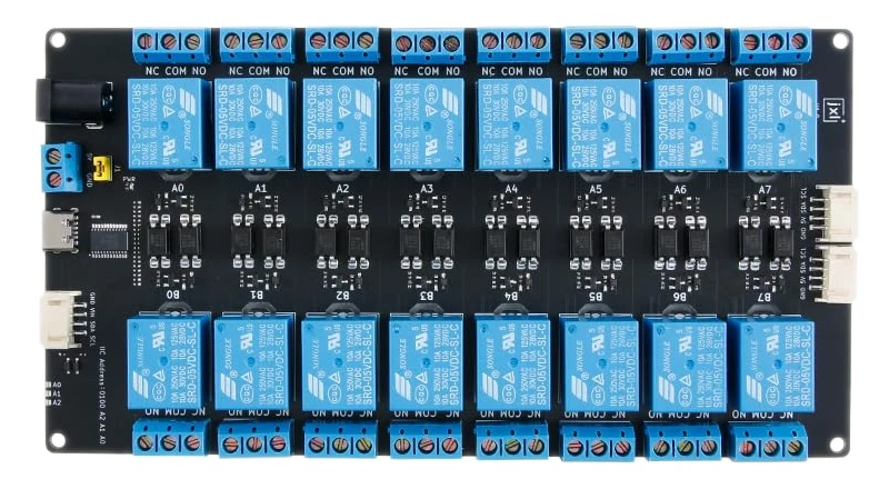
The RelayModuleI2C is a versatile electronic component designed to control high-voltage devices using low-voltage signals. It features an I2C interface, enabling seamless communication with microcontrollers such as Arduino, Raspberry Pi, and other platforms. This module typically includes multiple relays, each of which can be activated individually, making it ideal for applications requiring the switching of electrical loads.

Explore Projects Built with RelayModuleI2C

Use Cirkit Designer to design, explore, and prototype these projects online. Some projects support real-time simulation. Click "Open Project" to start designing instantly!
ESP32 and MCP23017-Based Smart Relay Control System with DHT22 Sensors
Image of Indoor Lounge: A project utilizing RelayModuleI2C in a practical application
This circuit is a control system that uses an ESP32 microcontroller to manage multiple relays and read data from DHT22 temperature and humidity sensors. The DFRobot Gravity MCP23017 I2C module expands the GPIO capabilities of the ESP32, allowing it to control additional relays for switching high-power devices.
Cirkit Designer LogoOpen Project in Cirkit Designer
ESP32-S3 Based Smart IoT Distance Sensor with Ethernet Connectivity
Image of ttt: A project utilizing RelayModuleI2C in a practical application
This circuit features an ESP32-S3 microcontroller interfaced with a KY-019 Relay module, a VL53L1X time-of-flight sensor, and a W5500 Ethernet module. The ESP32-S3 controls the relay and communicates with the VL53L1X sensor via I2C, as well as with the network through the Ethernet module. An AC source is converted to DC for powering the components, and a micro USB connection is used to trigger the relay.
Cirkit Designer LogoOpen Project in Cirkit Designer
ESP32-Controlled I2C LCD Display and Relay Module
Image of EV WIRELESS  CHRG: A project utilizing RelayModuleI2C in a practical application
This circuit features an ESP32 microcontroller interfaced with an I2C LCD 16x2 screen and a 2-channel relay module. The ESP32 controls the display of messages on the LCD screen and the switching of the relay channels. The code provided enables the ESP32 to initialize the LCD and cycle through displaying messages with delays, while the relay channels can be controlled via the ESP32's GPIO pins.
Cirkit Designer LogoOpen Project in Cirkit Designer
ESP8266 NodeMCU Controlled Smart Irrigation System with I2C LCD Display
Image of SIH_24: A project utilizing RelayModuleI2C in a practical application
This circuit is designed for a smart irrigation system that uses an ESP8266 NodeMCU to monitor soil moisture and ambient temperature/humidity, and display the data on an I2C LCD screen. It controls a water pump via a relay, which is activated when soil moisture falls below a threshold or manually via a tactile switch. The system aims to optimize water usage for precision farming by automating irrigation based on real-time environmental conditions.
Cirkit Designer LogoOpen Project in Cirkit Designer

Explore Projects Built with RelayModuleI2C

Use Cirkit Designer to design, explore, and prototype these projects online. Some projects support real-time simulation. Click "Open Project" to start designing instantly!
Image of Indoor Lounge: A project utilizing RelayModuleI2C in a practical application
ESP32 and MCP23017-Based Smart Relay Control System with DHT22 Sensors
This circuit is a control system that uses an ESP32 microcontroller to manage multiple relays and read data from DHT22 temperature and humidity sensors. The DFRobot Gravity MCP23017 I2C module expands the GPIO capabilities of the ESP32, allowing it to control additional relays for switching high-power devices.
Cirkit Designer LogoOpen Project in Cirkit Designer
Image of ttt: A project utilizing RelayModuleI2C in a practical application
ESP32-S3 Based Smart IoT Distance Sensor with Ethernet Connectivity
This circuit features an ESP32-S3 microcontroller interfaced with a KY-019 Relay module, a VL53L1X time-of-flight sensor, and a W5500 Ethernet module. The ESP32-S3 controls the relay and communicates with the VL53L1X sensor via I2C, as well as with the network through the Ethernet module. An AC source is converted to DC for powering the components, and a micro USB connection is used to trigger the relay.
Cirkit Designer LogoOpen Project in Cirkit Designer
Image of EV WIRELESS  CHRG: A project utilizing RelayModuleI2C in a practical application
ESP32-Controlled I2C LCD Display and Relay Module
This circuit features an ESP32 microcontroller interfaced with an I2C LCD 16x2 screen and a 2-channel relay module. The ESP32 controls the display of messages on the LCD screen and the switching of the relay channels. The code provided enables the ESP32 to initialize the LCD and cycle through displaying messages with delays, while the relay channels can be controlled via the ESP32's GPIO pins.
Cirkit Designer LogoOpen Project in Cirkit Designer
Image of SIH_24: A project utilizing RelayModuleI2C in a practical application
ESP8266 NodeMCU Controlled Smart Irrigation System with I2C LCD Display
This circuit is designed for a smart irrigation system that uses an ESP8266 NodeMCU to monitor soil moisture and ambient temperature/humidity, and display the data on an I2C LCD screen. It controls a water pump via a relay, which is activated when soil moisture falls below a threshold or manually via a tactile switch. The system aims to optimize water usage for precision farming by automating irrigation based on real-time environmental conditions.
Cirkit Designer LogoOpen Project in Cirkit Designer

Common Applications

  • Home automation systems (e.g., controlling lights, fans, or appliances)
  • Industrial automation (e.g., motor control, solenoid activation)
  • Robotics (e.g., controlling actuators or high-power components)
  • IoT projects requiring remote control of electrical devices

Technical Specifications

Below are the key technical details of the RelayModuleI2C:

Parameter Value
Operating Voltage 5V DC
Communication Protocol I2C
I2C Address Range 0x20 to 0x27 (configurable via jumpers)
Number of Relays 4 (can vary depending on the module)
Relay Voltage Rating 250V AC / 30V DC
Relay Current Rating 10A
Power Consumption ~70mA per active relay
Dimensions 50mm x 70mm x 20mm
Operating Temperature -40°C to 85°C

Pin Configuration

The RelayModuleI2C typically has the following pinout:

Pin Name Description
VCC Power supply input (5V DC)
GND Ground connection
SDA I2C data line
SCL I2C clock line
RELAY1 Normally Open (NO), Common (COM), Normally Closed (NC) for Relay 1
RELAY2 Normally Open (NO), Common (COM), Normally Closed (NC) for Relay 2
RELAY3 Normally Open (NO), Common (COM), Normally Closed (NC) for Relay 3
RELAY4 Normally Open (NO), Common (COM), Normally Closed (NC) for Relay 4

Usage Instructions

Connecting the RelayModuleI2C

  1. Power the Module: Connect the
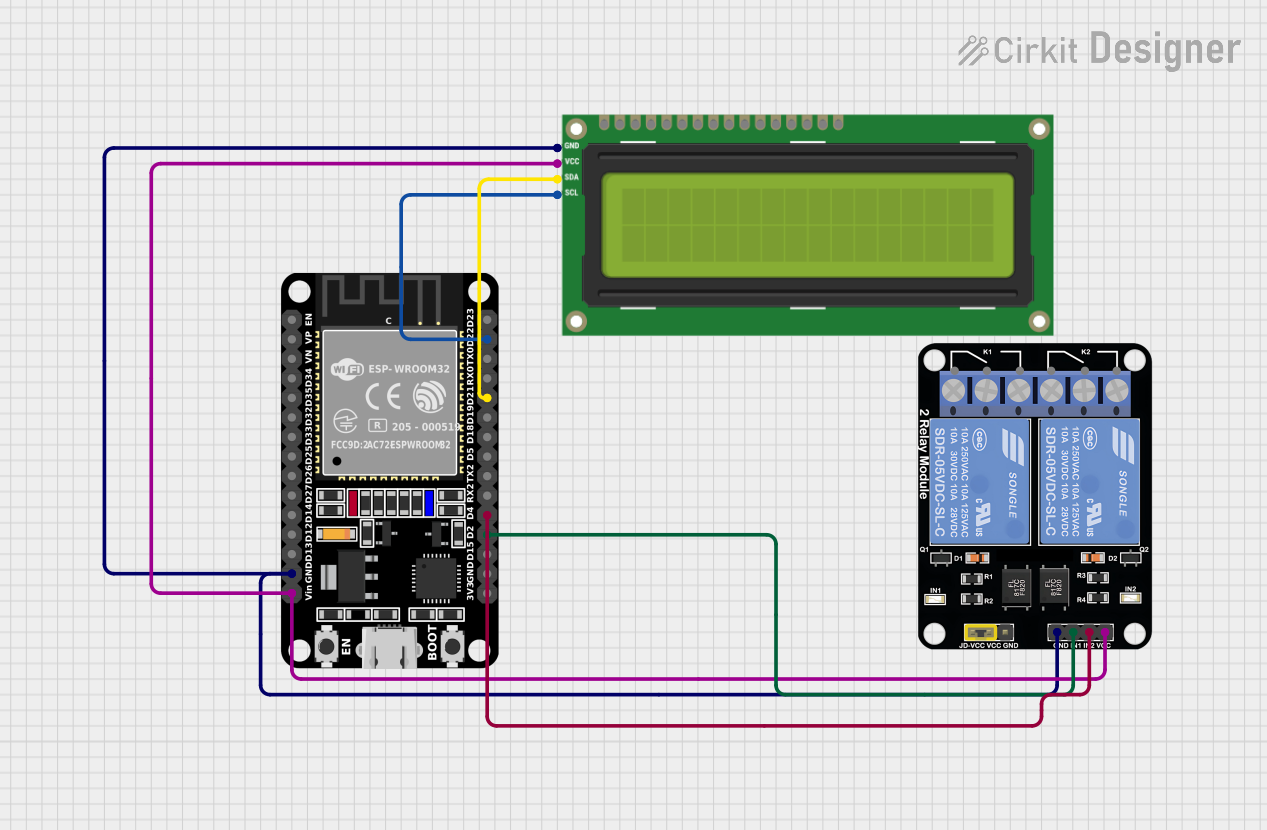
 VCC pin to a 5V power source and the GND pin to ground.
  2. I2C Communication: Connect the SDA and SCL pins to the corresponding I2C pins on your microcontroller:
    • For Arduino UNO: SDA → A4, SCL → A5
    • For other boards, refer to their I2C pinout.
  3. Load Connections: Connect the electrical load to the relay terminals (NO, COM, NC) as per your requirements:
    • Normally Open (NO): The circuit is open when the relay is inactive.
    • Normally Closed (NC): The circuit is closed when the relay is inactive.
    • Common (COM): The shared terminal for NO and NC.

Example Code for Arduino UNO

Below is an example code to control the RelayModuleI2C using an Arduino UNO:

#include <Wire.h> // Include the Wire library for I2C communication

#define RELAY_MODULE_ADDRESS 0x20 // Default I2C address of the module

void setup() {
  Wire.begin(); // Initialize I2C communication
  Serial.begin(9600); // Start serial communication for debugging

  // Set all relays to OFF initially
  Wire.beginTransmission(RELAY_MODULE_ADDRESS);
  Wire.write(0x00); // Send command to turn off all relays
  Wire.endTransmission();
  Serial.println("Relay Module Initialized");
}

void loop() {
  // Example: Turn on Relay 1
  Wire.beginTransmission(RELAY_MODULE_ADDRESS);
  Wire.write(0x01); // Command to activate Relay 1
  Wire.endTransmission();
  delay(1000); // Keep Relay 1 ON for 1 second

  // Example: Turn off Relay 1
  Wire.beginTransmission(RELAY_MODULE_ADDRESS);
  Wire.write(0x00); // Command to deactivate all relays
  Wire.endTransmission();
  delay(1000); // Wait for 1 second before repeating
}

Important Considerations

  • Power Supply: Ensure the module is powered with a stable 5V DC supply.
  • Load Ratings: Do not exceed the relay's voltage and current ratings (250V AC / 30V DC, 10A).
  • I2C Address: If using multiple RelayModuleI2C units, configure unique I2C addresses using the onboard jumpers.
  • Isolation: For safety, ensure proper isolation between the high-voltage and low-voltage sides of the circuit.

Troubleshooting and FAQs

Common Issues

  1. Relays Not Activating

    • Cause: Incorrect I2C address or wiring.
    • Solution: Verify the I2C address and ensure proper connections for SDA and SCL.
  2. Module Overheating

    • Cause: Exceeding the relay's current rating.
    • Solution: Ensure the connected load does not exceed 10A.
  3. No Response from Module

    • Cause: Faulty power supply or incorrect I2C configuration.
    • Solution: Check the power supply voltage and confirm the I2C address.

FAQs

  1. Can I use this module with a 3.3V microcontroller?

    • Yes, but you may need a level shifter for the I2C lines to ensure proper communication.
  2. How do I change the I2C address?

    • Use the onboard jumpers to set a new address within the range 0x20 to 0x27.
  3. Can I control multiple relays simultaneously?

    • Yes, send the appropriate command to activate multiple relays at once.
  4. Is the module safe for high-voltage applications?

    • Yes, but ensure proper insulation and follow safety guidelines when working with high voltages.

By following this documentation, you can effectively integrate the RelayModuleI2C into your projects and control high-voltage devices with ease.