How to Use GPS: Examples, Pinouts, and Specs
Introduction
A Global Positioning System (GPS) receiver determines the precise location of an object on Earth using signals from satellites. It calculates latitude, longitude, altitude, and time by triangulating signals from at least four satellites in the GPS constellation. GPS modules are widely used in navigation, tracking, and timing applications.
Explore Projects Built with GPS


Explore Projects Built with GPS
Common Applications and Use Cases
- Vehicle navigation systems
- Asset tracking and fleet management
- Outdoor sports and fitness devices
- Geotagging for photography
- Autonomous drones and robotics
- Time synchronization in communication networks
Technical Specifications
Below are the general technical specifications for a typical GPS module. Specifications may vary depending on the manufacturer and model.
| Parameter | Specification |
|---|---|
| Operating Voltage | 3.3V to 5V |
| Operating Current | 20mA to 50mA |
| Communication Protocol | UART (TTL), I2C, or SPI |
| Baud Rate (Default) | 9600 bps |
| Position Accuracy | ±2.5 meters (typical) |
| Time to First Fix (TTFF) | Cold Start: ~30 seconds, Hot Start: ~1 second |
| Antenna Type | External or built-in ceramic patch antenna |
| Operating Temperature | -40°C to +85°C |
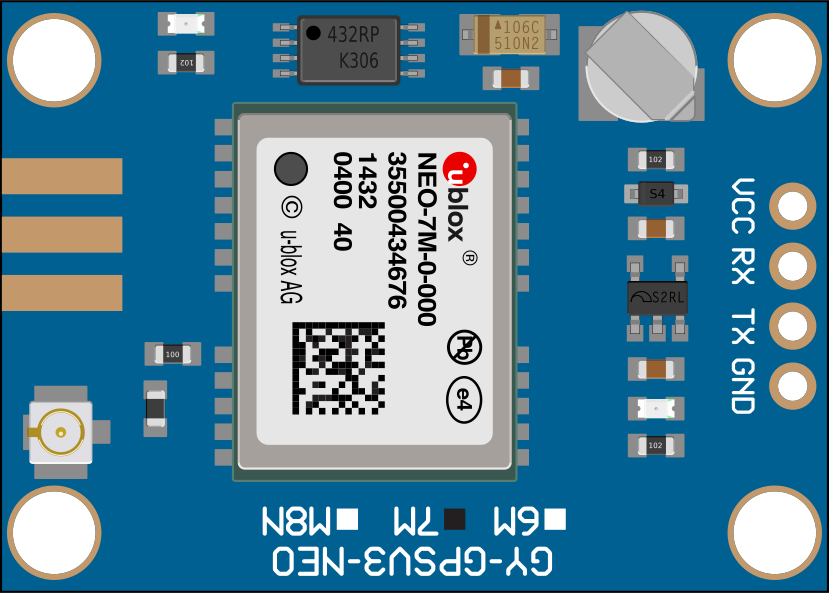
Pin Configuration and Descriptions
The pinout of a typical GPS module is as follows:
| Pin Name | Description |
|---|---|
| VCC | Power supply input (3.3V to 5V) |
| GND | Ground connection |
| TX | Transmit data (UART output) |
| RX | Receive data (UART input) |
| PPS | Pulse Per Second output for precise timing (optional) |
| EN | Enable pin to turn the module on/off (optional) |
Usage Instructions
How to Use the GPS Module in a Circuit
- Power the Module: Connect the VCC pin to a 3.3V or 5V power source and the GND pin to ground.
- Connect Communication Pins:
- For UART communication, connect the TX pin of the GPS module to the RX pin of your microcontroller (e.g., Arduino UNO) and the RX pin of the GPS module to the TX pin of the microcontroller.
- Ensure the baud rate of the microcontroller matches the GPS module's default baud rate (typically 9600 bps).
- Antenna Placement: If the module uses an external antenna, ensure it is placed in an open area with a clear view of the sky for optimal satellite signal reception.
- Read GPS Data: Use a microcontroller or computer to parse the NMEA sentences (standard GPS data format) transmitted by the module.
Important Considerations and Best Practices
- Signal Reception: GPS modules require a clear line of sight to satellites. Avoid using them indoors or in areas with heavy obstructions like tall buildings or dense forests.
- Power Supply: Ensure a stable power supply to avoid data corruption or module resets.
- Antenna Orientation: For best results, position the antenna facing upward toward the sky.
- Parsing NMEA Sentences: Use libraries or software tools to decode NMEA sentences into readable data like latitude, longitude, and time.
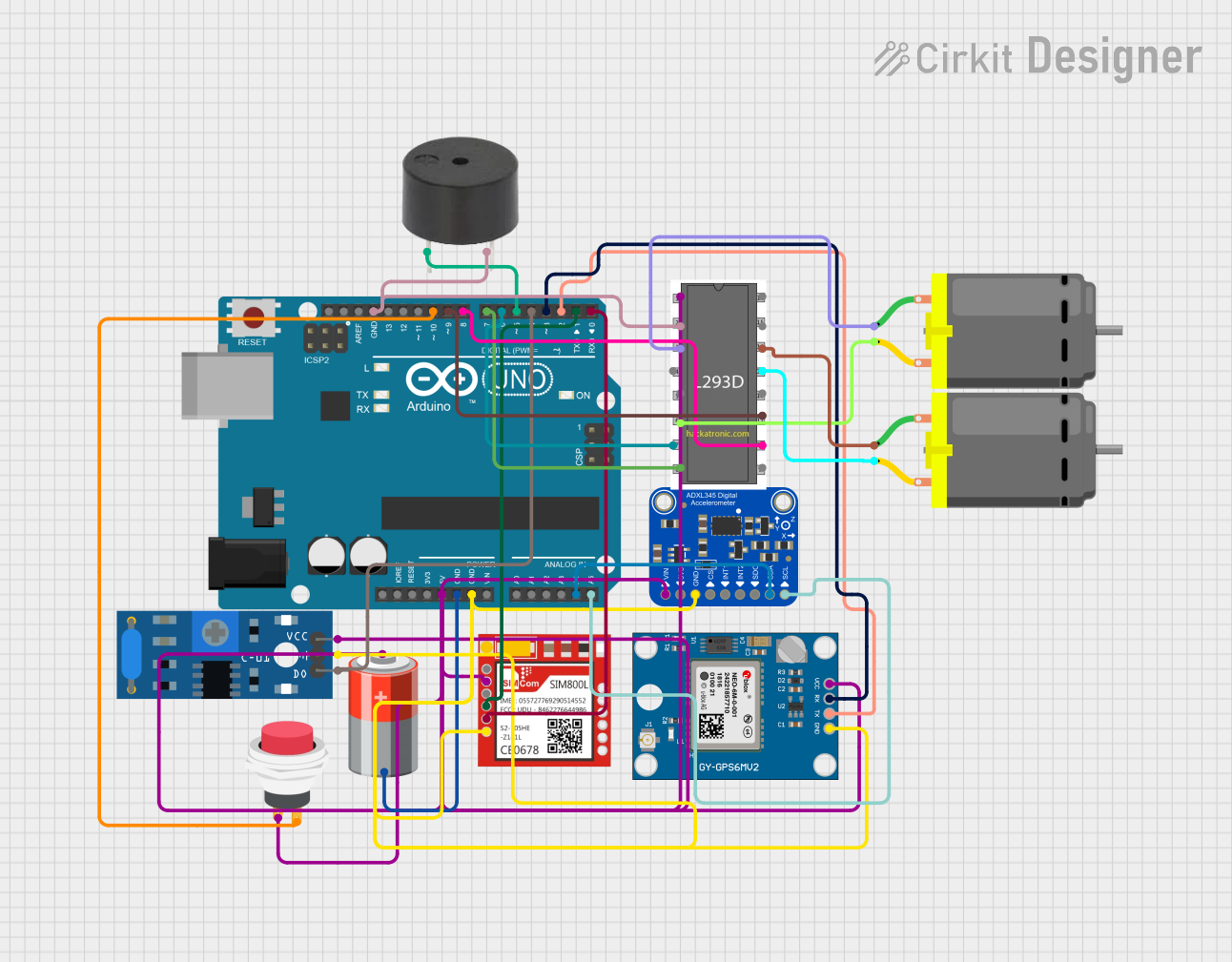
Example: Connecting GPS to Arduino UNO
Below is an example of how to connect and read data from a GPS module using an Arduino UNO.
Circuit Connections
- GPS VCC → Arduino 5V
- GPS GND → Arduino GND
- GPS TX → Arduino RX (Pin 0)
- GPS RX → Arduino TX (Pin 1)
Arduino Code
#include <SoftwareSerial.h>

// Define RX and TX pins for SoftwareSerial
SoftwareSerial gpsSerial(4, 3); // RX = Pin 4, TX = Pin 3

void setup() {
  Serial.begin(9600); // Initialize Serial Monitor at 9600 bps
  gpsSerial.begin(9600); // Initialize GPS module at 9600 bps
  Serial.println("GPS Module Initialized");
}

void loop() {
  // Check if data is available from the GPS module
  while (gpsSerial.available()) {
    char c = gpsSerial.read(); // Read one character from GPS
    Serial.print(c); // Print the character to the Serial Monitor
  }
}
Note: The above code uses the
SoftwareSeriallibrary to communicate with the GPS module on pins 4 and 3 of the Arduino UNO. Ensure the GPS module's baud rate matches the one specified in the code.
Troubleshooting and FAQs
Common Issues and Solutions
No GPS Data Received
- Cause: Incorrect wiring or baud rate mismatch.
- Solution: Double-check the connections and ensure the baud rate in your code matches the GPS module's default baud rate.
Poor Signal Reception
- Cause: Obstructions or poor antenna placement.
- Solution: Move the GPS module to an open area with a clear view of the sky. Ensure the antenna is properly connected and oriented.
Module Not Powering On
- Cause: Insufficient or unstable power supply.
- Solution: Verify the power source and ensure it meets the module's voltage and current requirements.
Garbage Data in Serial Monitor
- Cause: Baud rate mismatch or incorrect Serial Monitor settings.
- Solution: Set the Serial Monitor baud rate to match the GPS module's baud rate (e.g., 9600 bps).
FAQs
Q1: Can I use the GPS module indoors?
A1: GPS modules generally perform poorly indoors due to signal obstructions. For indoor positioning, consider alternatives like Wi-Fi or Bluetooth-based location systems.
Q2: How many satellites are required for accurate positioning?
A2: A minimum of four satellites is required for 3D positioning (latitude, longitude, and altitude). More satellites improve accuracy.
Q3: Can I change the default baud rate of the GPS module?
A3: Yes, many GPS modules allow you to configure the baud rate using specific commands. Refer to the module's datasheet for instructions.
Q4: What is the purpose of the PPS pin?
A4: The PPS (Pulse Per Second) pin provides a precise timing signal, often used in time-sensitive applications like synchronization of communication networks.