How to Use Raspberry Pi 4 B: Examples, Pinouts, and Specs
Introduction
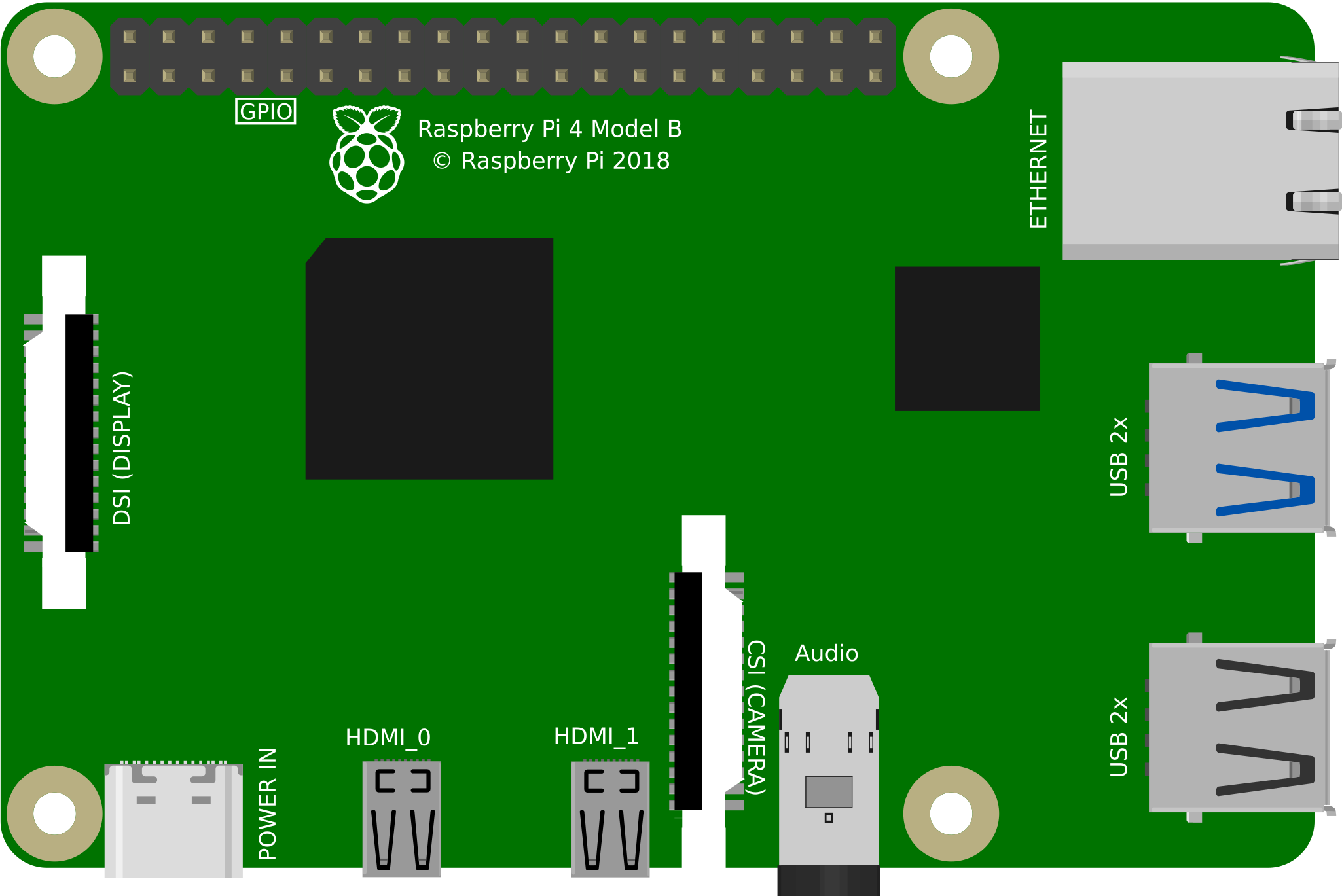
The Raspberry Pi 4 B is a compact, affordable single-board computer designed for a wide range of applications. It features a powerful quad-core processor, up to 8GB of RAM, USB 3.0 ports, dual-band Wi-Fi, and dual micro-HDMI outputs. This versatile device is ideal for projects such as programming, media centers, IoT applications, robotics, and more. Its small form factor and robust performance make it a popular choice for both hobbyists and professionals.
Explore Projects Built with Raspberry Pi 4 B
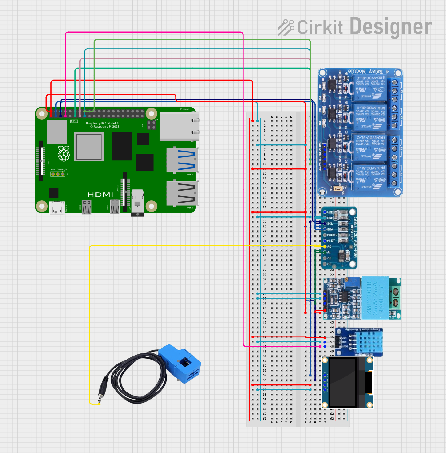
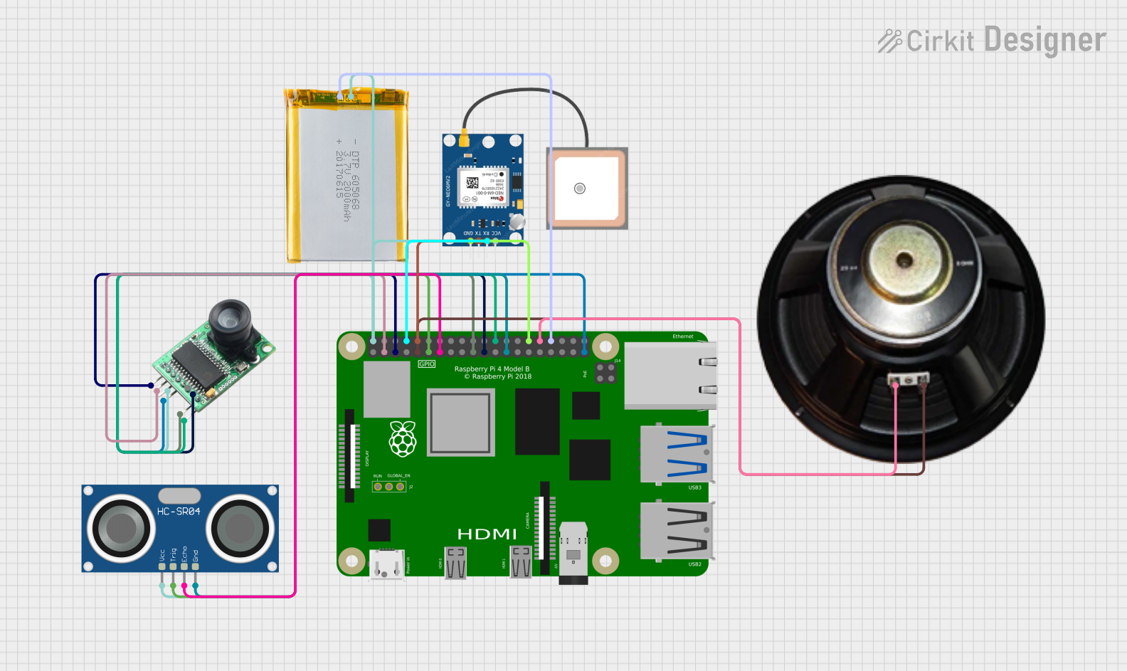
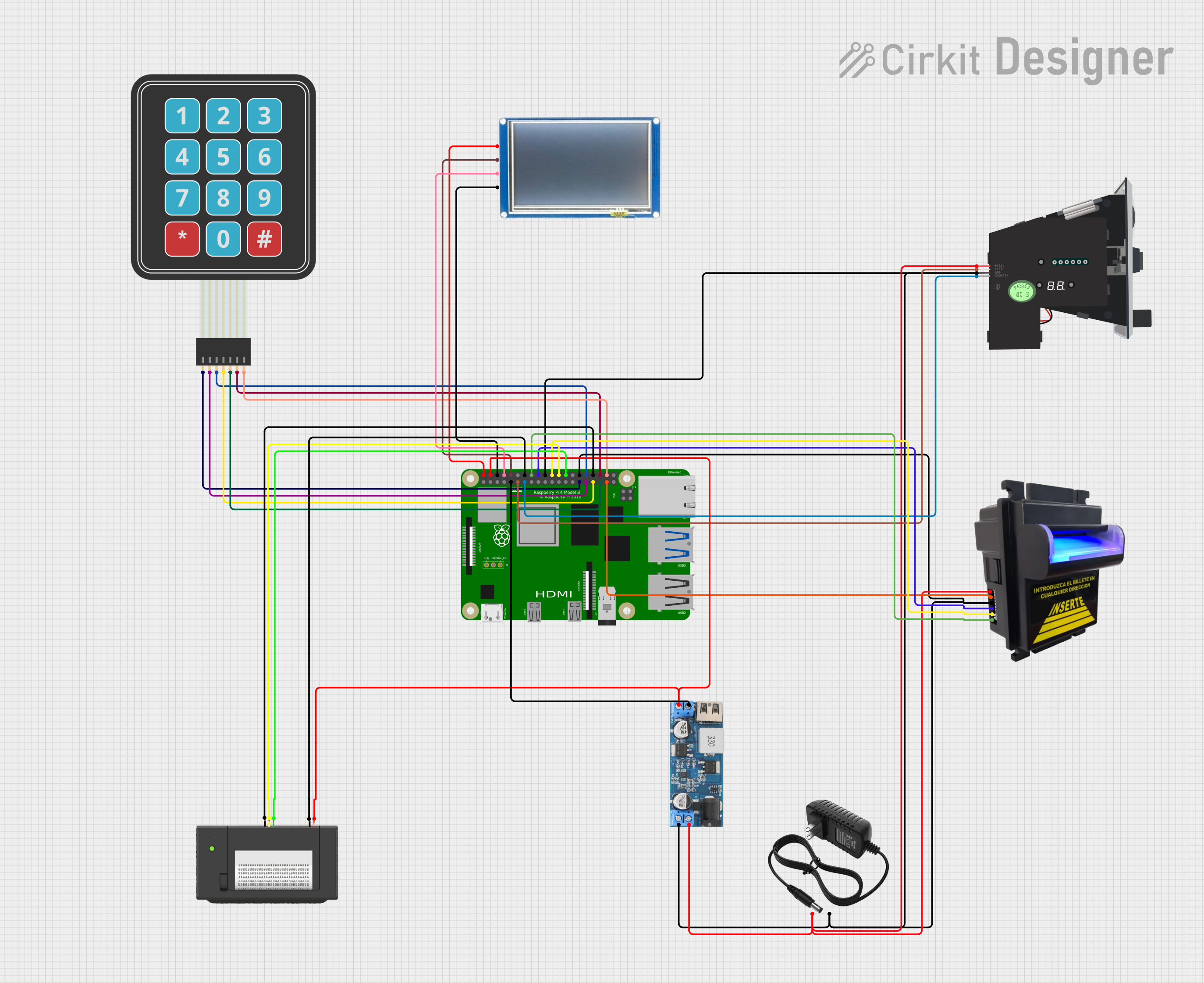
Explore Projects Built with Raspberry Pi 4 B
Common Applications and Use Cases
- Programming and Education: Ideal for learning programming languages like Python, C++, and Java.
- Media Centers: Can be used to build a home theater system with software like Kodi.
- IoT Projects: Acts as a hub for Internet of Things devices and sensors.
- Robotics: Powers robots with its GPIO pins and processing capabilities.
- Web Servers: Can host lightweight web servers for personal or small-scale projects.
- AI and Machine Learning: Suitable for running lightweight AI models and edge computing tasks.
Technical Specifications
Key Technical Details
| Specification | Details |
|---|---|
| Processor | Broadcom BCM2711, Quad-core Cortex-A72 (ARM v8) 64-bit SoC @ 1.5GHz |
| RAM Options | 2GB, 4GB, or 8GB LPDDR4-3200 SDRAM |
| Storage | MicroSD card slot for storage and operating system |
| USB Ports | 2 × USB 3.0, 2 × USB 2.0 |
| Networking | Gigabit Ethernet, Dual-band 802.11ac Wi-Fi, Bluetooth 5.0 |
| Video Output | 2 × micro-HDMI ports (up to 4Kp60 supported) |
| GPIO | 40-pin GPIO header, backward-compatible with previous Raspberry Pi models |
| Power Supply | 5V/3A via USB-C connector |
| Dimensions | 85.6mm × 56.5mm × 17mm |
Pin Configuration and Descriptions
The Raspberry Pi 4 B features a 40-pin GPIO header. Below is a summary of the pin configuration:
| Pin Number | Pin Name | Function | Voltage Level |
|---|---|---|---|
| 1 | 3.3V Power | Power Supply | 3.3V |
| 2 | 5V Power | Power Supply | 5V |
| 3 | GPIO2 (SDA1) | I2C Data | 3.3V |
| 4 | 5V Power | Power Supply | 5V |
| 5 | GPIO3 (SCL1) | I2C Clock | 3.3V |
| 6 | Ground | Ground | 0V |
| ... | ... | ... | ... |
| 39 | Ground | Ground | 0V |
| 40 | GPIO21 | General Purpose I/O | 3.3V |
For a complete GPIO pinout, refer to the official Raspberry Pi documentation.
Usage Instructions
How to Use the Raspberry Pi 4 B in a Circuit
- Powering the Raspberry Pi: Use a 5V/3A USB-C power supply to power the board. Ensure the power supply is reliable to avoid voltage drops.
- Connecting Peripherals: Attach a monitor via the micro-HDMI ports, a keyboard and mouse via USB ports, and a microSD card with the operating system installed.
- Using GPIO Pins: Connect sensors, LEDs, or other components to the GPIO pins. Be cautious about voltage levels to avoid damaging the board.
- Networking: Use the built-in Wi-Fi or Ethernet port for internet connectivity.
Important Considerations and Best Practices
- Cooling: The Raspberry Pi 4 B can get warm under heavy loads. Use a heatsink or fan for better thermal management.
- Operating System: Install Raspberry Pi OS (formerly Raspbian) or other compatible operating systems on a microSD card.
- Power Supply: Always use a high-quality power supply to ensure stable operation.
- GPIO Safety: Avoid connecting components that exceed the 3.3V GPIO voltage limit.
Example: Blinking an LED with GPIO and Python
Below is an example of how to blink an LED connected to GPIO pin 17 using Python:
Import necessary libraries
import RPi.GPIO as GPIO import time
Set up GPIO mode and pin
GPIO.setmode(GPIO.BCM) # Use Broadcom pin numbering GPIO.setup(17, GPIO.OUT) # Set GPIO pin 17 as an output
try: while True: GPIO.output(17, GPIO.HIGH) # Turn LED on time.sleep(1) # Wait for 1 second GPIO.output(17, GPIO.LOW) # Turn LED off time.sleep(1) # Wait for 1 second except KeyboardInterrupt: # Clean up GPIO settings on exit GPIO.cleanup()
Running the Code
- Connect an LED to GPIO pin 17 with a 330-ohm resistor in series.
- Save the code to a file (e.g.,
blink.py). - Run the script using the command:
python3 blink.py.
Troubleshooting and FAQs
Common Issues and Solutions
The Raspberry Pi does not boot:
- Ensure the microSD card is properly inserted and contains a valid operating system.
- Check the power supply for sufficient voltage and current.
Overheating:
- Use a heatsink or fan to improve cooling.
- Avoid running resource-intensive tasks for extended periods without proper cooling.
No display output:
- Verify the micro-HDMI cable is securely connected.
- Ensure the monitor is set to the correct input source.
GPIO pins not working:
- Double-check the pin connections and ensure the correct GPIO numbering is used in the code.
- Avoid exceeding the 3.3V limit on GPIO pins.
FAQs
Can I power the Raspberry Pi 4 B via GPIO pins? Yes, you can power it via the 5V and GND pins, but this bypasses the onboard voltage protection.
What is the maximum resolution supported? The Raspberry Pi 4 B supports up to dual 4Kp60 output via its micro-HDMI ports.
Can I use older Raspberry Pi accessories with the Raspberry Pi 4 B? Most accessories are compatible, but check for specific requirements like power and GPIO pinout differences.
This documentation provides a comprehensive guide to using the Raspberry Pi 4 B effectively. For further details, refer to the official Raspberry Pi website.