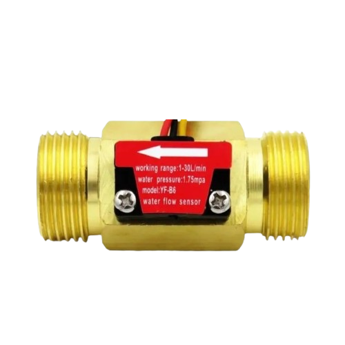
The YF-B6 is a flow sensor designed for fluid measurement applications. It features a compact and durable design, making it ideal for use in systems requiring accurate liquid flow rate monitoring. The sensor operates by generating a pulse signal proportional to the flow rate, which can be easily interpreted by microcontrollers or other control systems. Its versatility and reliability make it a popular choice for automation, irrigation, water dispensing, and industrial fluid monitoring.
Explore Projects Built with YF-b6
Use Cirkit Designer to design, explore, and prototype these projects online. Some projects support real-time simulation. Click "Open Project" to start designing instantly!
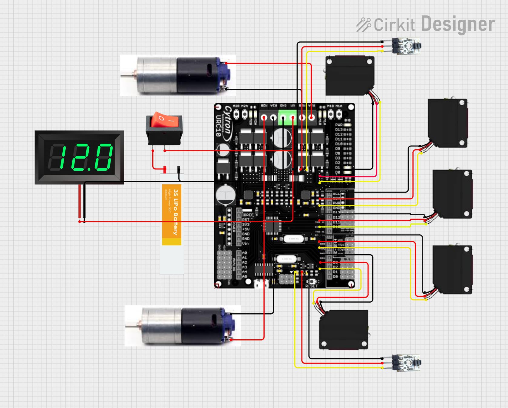
This circuit is a robotic control system that uses multiple IR sensors for line detection and obstacle avoidance, powered by a 3S LiPo battery. The Cytron URC10 motor driver, controlled by a microcontroller, drives two GM25 DC motors based on input from the sensors and a rocker switch, with a 7-segment panel voltmeter displaying the battery voltage.
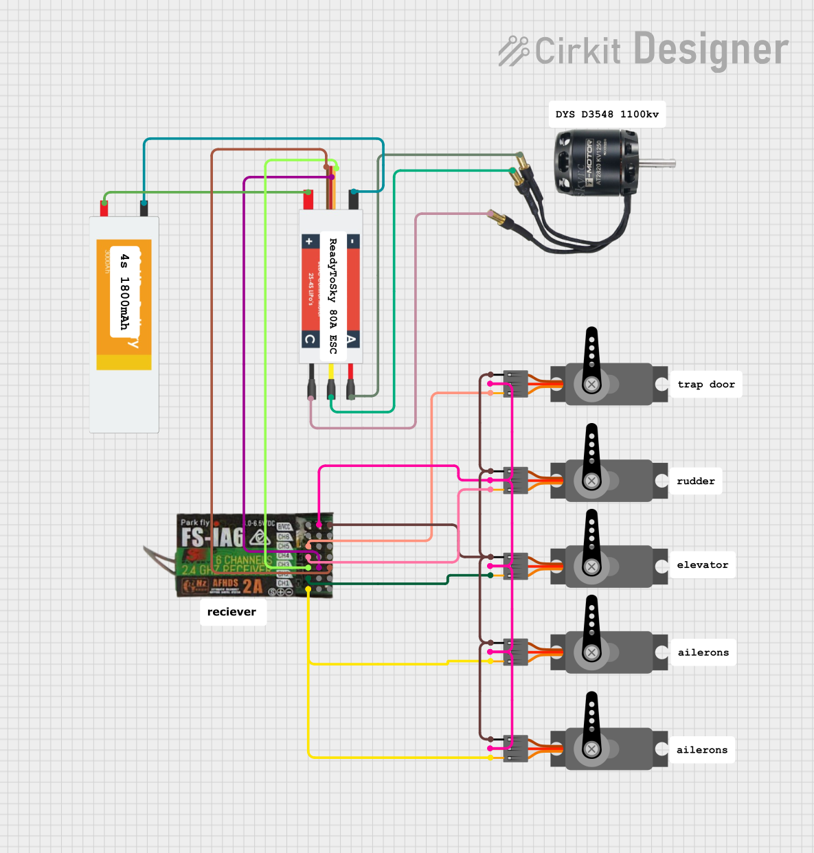
This circuit is designed to control a BLDC motor and multiple servos using an Electronic Speed Controller (ESC) and a FlySky FS-IA6 receiver. The ESC regulates the power from a LiPo battery to the BLDC motor, while the FlySky receiver provides PWM signals to control the servos and the ESC.
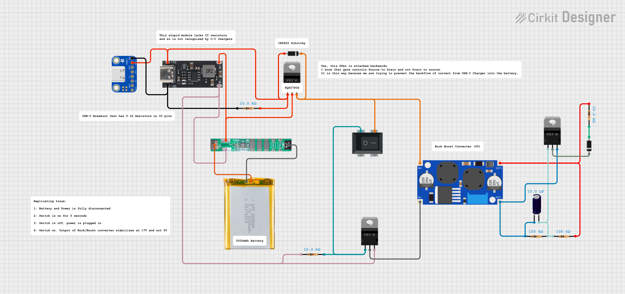
This circuit is a power management and conversion system that includes a boost converter, battery management system (BMS), and various MOSFETs and passive components. It is designed to regulate and boost the voltage from a 2000mAh battery, providing stable power output through a USB Type C interface. The circuit also includes protection and switching mechanisms to ensure safe and efficient power delivery.
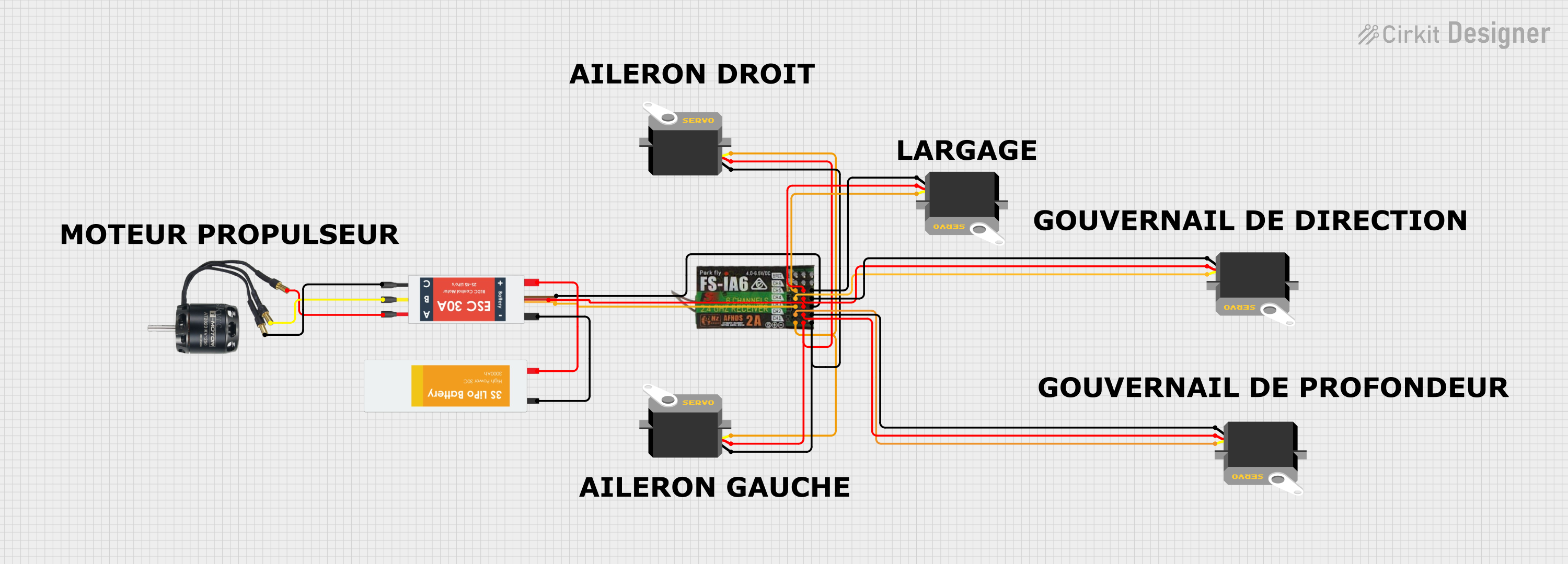
This circuit is designed to control a BLDC motor and multiple servos using a FLYSKY FS-IA6 receiver. The Electronic Speed Controller (ESC) is powered by a LiPo battery and drives the BLDC motor, while the servos are powered and controlled by the receiver channels.
The YF-B6 flow sensor is designed to provide reliable and accurate measurements. Below are its key technical details:
Parameter
Specification
Operating Voltage
5V to 18V DC
Output Signal
Pulse signal (square wave)
Flow Rate Range
1 to 30 liters per minute (L/min)
Accuracy
±2%
Maximum Pressure
≤ 1.75 MPa
Operating Temperature
-25°C to 80°C
Output Duty Cycle
50% ±10%
Pulse Frequency
7.5 * Flow Rate (L/min) (approx.)
Connector Type
3-pin JST
Pin Configuration
The YF-B6 has a 3-pin connector for interfacing with external circuits. The pinout is as follows:
Pin
Name
Description
1
VCC
Power supply input (5V to 18V DC)
2
GND
Ground connection
3
Signal
Pulse output signal proportional to the flow rate
Usage Instructions
How to Use the YF-B6 in a Circuit
Power Supply: Connect the VCC pin to a DC power source (5V to 18V). Ensure the power supply is stable to avoid inaccurate readings.
Ground Connection: Connect the GND pin to the ground of your circuit.
Signal Output: Connect the Signal pin to a microcontroller's digital input pin or a frequency counter. The sensor outputs a pulse signal, where the frequency is proportional to the flow rate.
Example Circuit with Arduino UNO
Below is an example of how to connect and use the YF-B6 with an Arduino UNO:
Circuit Connections
Connect the VCC pin of the YF-B6 to the 5V pin on the Arduino.
Connect the GND pin of the YF-B6 to the GND pin on the Arduino.
Connect the Signal pin of the YF-B6 to digital pin 2 on the Arduino.
Example Code
// YF-B6 Flow Sensor Example Code
// This code reads the pulse signal from the YF-B6 and calculates the flow rate.

volatile int pulseCount = 0; // Variable to store the pulse count
float flowRate = 0.0;        // Variable to store the calculated flow rate
unsigned long lastTime = 0;  // Variable to store the last time the flow was calculated

void setup() {
  pinMode(2, INPUT_PULLUP);  // Set pin 2 as input with pull-up resistor
  attachInterrupt(digitalPinToInterrupt(2), countPulse, RISING);
  // Attach interrupt to count pulses on pin 2
  Serial.begin(9600);        // Initialize serial communication
}

void loop() {
  unsigned long currentTime = millis(); // Get the current time
  if (currentTime - lastTime >= 1000) { // Calculate flow rate every second
    noInterrupts();                     // Disable interrupts temporarily
    float frequency = pulseCount;       // Get the pulse count
    pulseCount = 0;                     // Reset the pulse count
    interrupts();                       // Re-enable interrupts

    flowRate = (frequency / 7.5);       // Calculate flow rate in L/min
    Serial.print("Flow Rate: ");
    Serial.print(flowRate);
    Serial.println(" L/min");

    lastTime = currentTime;             // Update the last time
  }
}

void countPulse() {
  pulseCount++; // Increment pulse count on each rising edge
}
Important Considerations
Debouncing: The pulse signal may have noise or bouncing. Use software debouncing or filtering if necessary.
Orientation: Install the sensor in the correct orientation as specified by the manufacturer to ensure accurate readings.
Flow Direction: Ensure the liquid flows in the direction indicated by the arrow on the sensor body.
Power Supply: Use a stable power supply to avoid fluctuations in the output signal.
Troubleshooting and FAQs
Common Issues and Solutions
No Output Signal
Cause: Incorrect wiring or insufficient power supply.
Solution: Verify the wiring connections and ensure the power supply voltage is within the specified range (5V to 18V).
Inaccurate Flow Rate Readings
Cause: Air bubbles in the liquid or incorrect installation orientation.
Solution: Remove air bubbles and ensure the sensor is installed in the correct orientation.
Signal Noise or Fluctuations
Cause: Electrical noise or unstable power supply.
Solution: Use a decoupling capacitor across the power supply pins and ensure a stable power source.
Sensor Not Responding
Cause: Damaged sensor or incorrect flow direction.
Solution: Check for physical damage and ensure the liquid flows in the correct direction.
FAQs
Q1: Can the YF-B6 measure flow rates below 1 L/min?
A1: No, the YF-B6 is designed to measure flow rates within the range of 1 to 30 L/min. For lower flow rates, consider using a different sensor.
Q2: Is the YF-B6 suitable for measuring hot liquids?
A2: Yes, the YF-B6 can operate at temperatures up to 80°C. However, ensure the liquid temperature does not exceed this limit.
Q3: How do I calculate the total volume of liquid passed?
A3: Multiply the flow rate (L/min) by the time (in minutes) to calculate the total volume. Alternatively, count the total number of pulses and use the formula: Total Volume (L) = Total Pulses / (7.5 * 60).
Q4: Can the YF-B6 be used with liquids other than water?
A4: The YF-B6 is primarily designed for water. Using it with other liquids may affect accuracy and durability. Check the manufacturer's specifications for compatibility.

 Open Project in Cirkit Designer