
How to Use PCM5122: Examples, Pinouts, and Specs
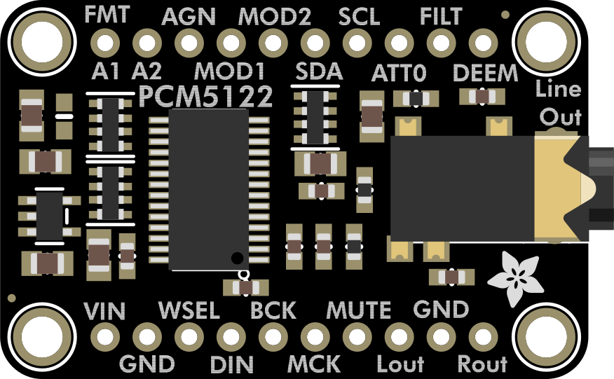
 Design with PCM5122 in Cirkit Designer
Introduction
The PCM5122 is a high-performance digital-to-analog converter (DAC) designed for audio applications. It features a 24-bit resolution and supports sample rates up to 192 kHz, ensuring high-fidelity audio playback. The component includes integrated digital filters and supports various audio formats, making it a versatile choice for audio systems. Its low noise and distortion characteristics make it ideal for applications such as home audio systems, professional audio equipment, and portable audio devices.
Explore Projects Built with PCM5122
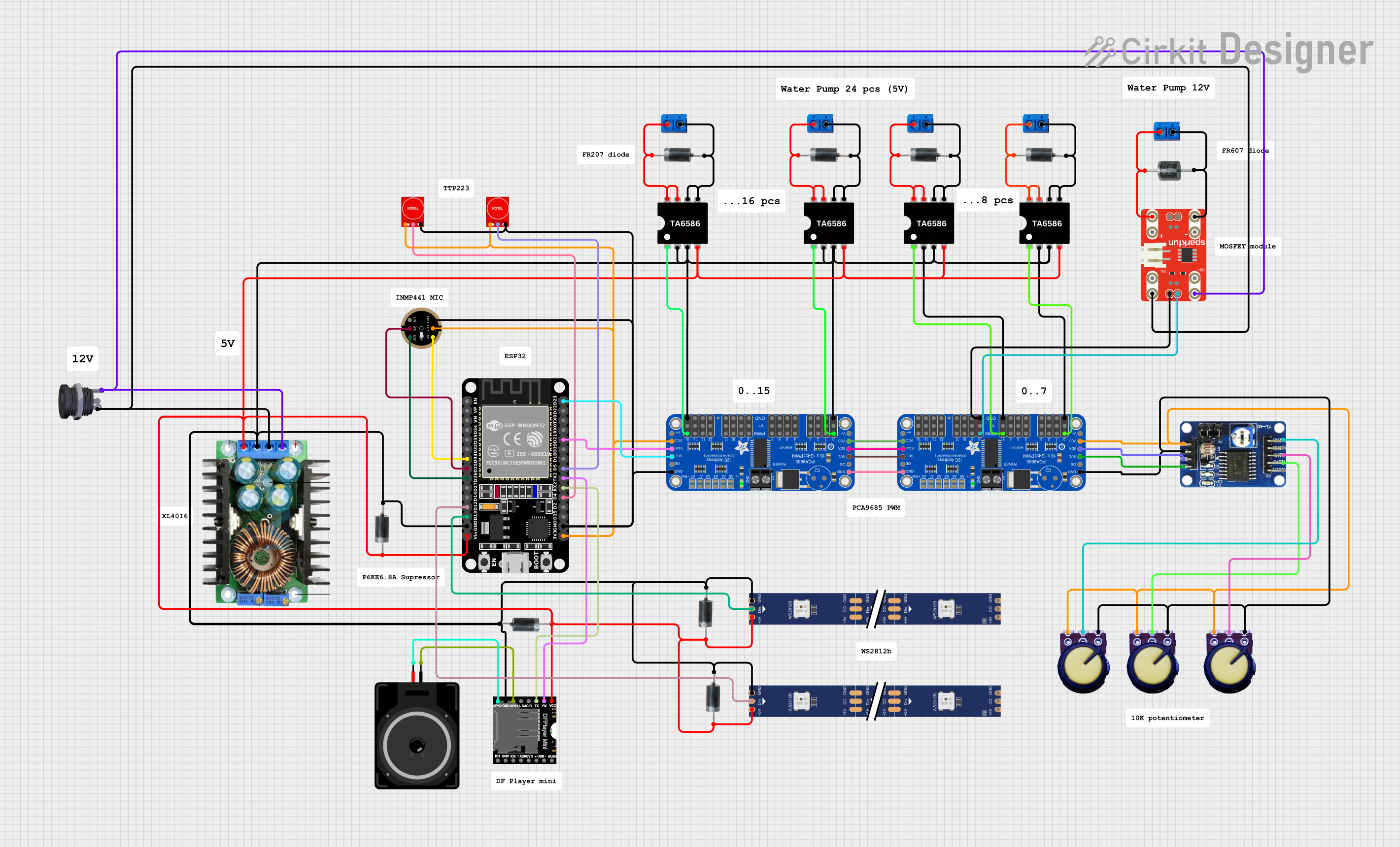
 Open Project in Cirkit Designer
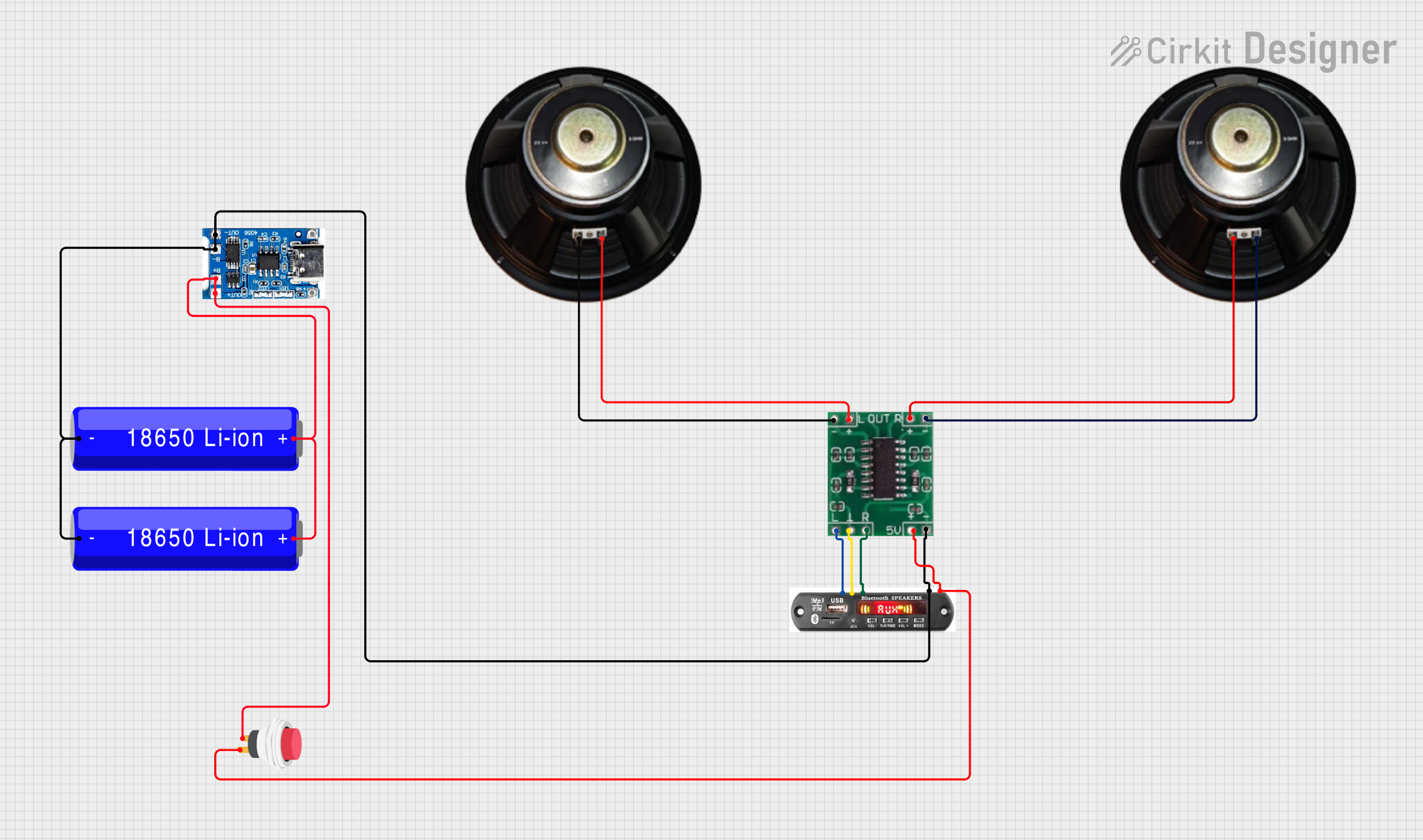
 Open Project in Cirkit Designer
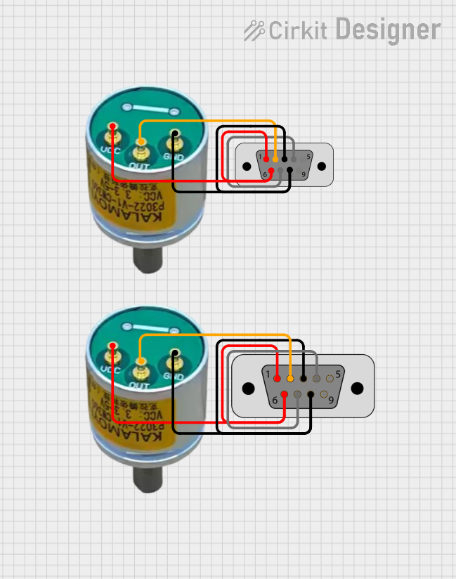
 Open Project in Cirkit Designer
 Open Project in Cirkit Designer
Explore Projects Built with PCM5122
Open Project in Cirkit DesignerOpen Project in Cirkit DesignerOpen Project in Cirkit DesignerOpen Project in Cirkit DesignerCommon Applications:
- High-fidelity audio playback systems
- Home theater receivers
- Professional audio equipment
- Portable audio devices
- Digital music players
Technical Specifications
Key Technical Details:
| Parameter | Value |
|---|---|
| Resolution | 24-bit |
| Maximum Sample Rate | 192 kHz |
| Signal-to-Noise Ratio (SNR) | 112 dB (typical) |
| Total Harmonic Distortion + Noise (THD+N) | -93 dB (typical) |
| Power Supply Voltage | 3.3V (analog and digital) |
| Output Voltage | 2.1 Vrms (typical) |
| Digital Audio Interfaces | I2S, Left-Justified, Right-Justified |
| Integrated Features | Digital filters, volume control, mute |
| Package Type | TSSOP-28 |
Pin Configuration and Descriptions:
The PCM5122 is available in a 28-pin TSSOP package. Below is the pin configuration:
| Pin Number | Pin Name | Description |
|---|---|---|
| 1 | DVDD | Digital power supply (3.3V) |
| 2 | DGND | Digital ground |
| 3 | LRCK | Left/Right clock input |
| 4 | BCK | Bit clock input |
| 5 | DIN | Digital audio data input |
| 6 | SCL | I2C clock input |
| 7 | SDA | I2C data input/output |
| 8 | RESET | Reset input (active low) |
| 9 | FMT | Audio format selection |
| 10 | MUTE | Mute control input |
| 11 | AVDD | Analog power supply (3.3V) |
| 12 | AGND | Analog ground |
| 13-14 | NC | No connection |
| 15-16 | VOUTL | Left channel analog output |
| 17-18 | VOUTR | Right channel analog output |
| 19 | XTI | External clock input |
| 20 | XTO | External clock output |
| 21 | PLLGND | PLL ground |
| 22 | PLLVDD | PLL power supply (3.3V) |
| 23 | GPIO1 | General-purpose I/O 1 |
| 24 | GPIO2 | General-purpose I/O 2 |
| 25 | GPIO3 | General-purpose I/O 3 |
| 26 | GPIO4 | General-purpose I/O 4 |
| 27 | NC | No connection |
| 28 | NC | No connection |
Usage Instructions
How to Use the PCM5122 in a Circuit:
- Power Supply: Connect the analog (AVDD) and digital (DVDD) power supply pins to a stable 3.3V source. Ensure proper decoupling capacitors are placed near the power pins to minimize noise.
- Grounding: Connect all ground pins (AGND, DGND, PLLGND) to a common ground plane to reduce noise and interference.
- Audio Input: Provide digital audio data to the DIN pin using an I2S, Left-Justified, or Right-Justified format. Configure the audio format using the FMT pin or via I2C.
- Clock Signals: Provide a bit clock (BCK) and left/right clock (LRCK) to synchronize the audio data. Optionally, use an external clock source connected to the XTI pin.
- Analog Output: Connect the VOUTL and VOUTR pins to the left and right audio output channels, respectively. Use appropriate filtering and amplification circuits if needed.
- Control Interface: Use the I2C interface (SCL and SDA pins) to configure the PCM5122 settings, such as volume control, digital filters, and mute functionality.
Important Considerations:
- Decoupling: Use low-ESR capacitors for decoupling the power supply pins to minimize noise.
- Clock Stability: Ensure the clock signals (BCK, LRCK, XTI) are stable and free from jitter to maintain audio quality.
- Reset: Use the RESET pin to initialize the PCM5122 during power-up or after a fault condition.
- Mute Control: Use the MUTE pin to silence the output during transitions or when no audio data is available.
Example: Connecting PCM5122 to an Arduino UNO
The PCM5122 can be controlled via I2C using an Arduino UNO. Below is an example code snippet to configure the PCM5122:
#include <Wire.h> // Include the Wire library for I2C communication

#define PCM5122_I2C_ADDRESS 0x4C // Default I2C address of PCM5122

void setup() {
  Wire.begin(); // Initialize I2C communication
  Serial.begin(9600); // Initialize serial communication for debugging

  // Configure PCM5122 registers via I2C
  Wire.beginTransmission(PCM5122_I2C_ADDRESS);
  Wire.write(0x00); // Select page 0
  Wire.write(0x01); // Example: Set a specific register (e.g., mute control)
  Wire.endTransmission();

  Serial.println("PCM5122 initialized.");
}

void loop() {
  // Main loop can be used to send additional commands or monitor status
}
Notes:
- Replace the register address and values in the code with the desired configuration for your application.
- Ensure pull-up resistors (typically 4.7kΩ) are connected to the I2C lines (SCL and SDA).
Troubleshooting and FAQs
Common Issues:
No Audio Output:
- Verify that the power supply voltages (AVDD, DVDD) are correct and stable.
- Check the clock signals (BCK, LRCK) for proper frequency and stability.
- Ensure the digital audio data format matches the PCM5122 configuration.
Distorted Audio:
- Check for noise or jitter in the clock signals.
- Verify that the analog output is properly filtered and amplified.
I2C Communication Failure:
- Ensure the I2C address matches the PCM5122's configured address.
- Check the pull-up resistors on the I2C lines.
Device Not Responding:
- Verify the RESET pin is properly initialized during power-up.
- Check all connections and ensure no pins are left floating.
FAQs:
Q: Can the PCM5122 operate without an external clock?
A: Yes, the PCM5122 has an internal PLL that can generate the required clock signals. However, for optimal performance, an external clock is recommended.
Q: What is the maximum output voltage of the PCM5122?
A: The typical maximum output voltage is 2.1 Vrms.
Q: Can I use the PCM5122 with a 5V power supply?
A: No, the PCM5122 requires a 3.3V power supply for both analog and digital sections.
Q: How do I configure the digital filters?
A: The digital filters can be configured via the I2C interface by writing to the appropriate registers.
Q: Is the PCM5122 compatible with other microcontrollers?
A: Yes, the PCM5122 can be used with any microcontroller that supports I2C or provides the required clock and data signals.