How to Use MIKROE-4469: Examples, Pinouts, and Specs
Introduction
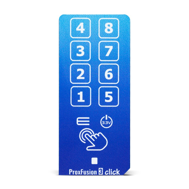
The MIKROE-4469 is a versatile development board manufactured by MikroElektronika. It is part of the MikroElektronika Click board ecosystem, which is designed to simplify prototyping and testing of electronic circuits. This board provides a variety of interfaces, making it easy to integrate with microcontrollers and other devices. Its modular design allows users to quickly test and develop applications without the need for complex wiring or soldering.
Explore Projects Built with MIKROE-4469


Explore Projects Built with MIKROE-4469
Common Applications and Use Cases
- Rapid prototyping of embedded systems
- Testing and evaluation of sensors, actuators, and communication modules
- Educational purposes for learning embedded systems and electronics
- Development of IoT (Internet of Things) applications
- Integration with microcontrollers such as Arduino, STM32, and Raspberry Pi
Technical Specifications
The MIKROE-4469 development board is designed to provide flexibility and ease of use. Below are its key technical details:
Key Technical Details
- Manufacturer Part ID: 1471-MIKROE-4469-ND
- Power Supply Voltage: 3.3V or 5V (selectable)
- Interfaces: SPI, I2C, UART, GPIO
- Compatibility: MikroElektronika Click boards
- Dimensions: Compact form factor for easy integration
- Connector Type: Standard Click board socket
- Operating Temperature: -40°C to +85°C
Pin Configuration and Descriptions
The MIKROE-4469 features a standard Click board socket with the following pin configuration:
| Pin Name | Description | Direction | Voltage Level |
|---|---|---|---|
| AN | Analog Input | Input | 0-3.3V or 0-5V |
| RST | Reset Signal | Input | 3.3V or 5V |
| CS | Chip Select (SPI) | Input | 3.3V or 5V |
| SCK | Serial Clock (SPI) | Input | 3.3V or 5V |
| MISO | Master In Slave Out (SPI) | Output | 3.3V or 5V |
| MOSI | Master Out Slave In (SPI) | Input | 3.3V or 5V |
| PWM | Pulse Width Modulation | Output | 3.3V or 5V |
| INT | Interrupt Signal | Output | 3.3V or 5V |
| RX | UART Receive | Input | 3.3V or 5V |
| TX | UART Transmit | Output | 3.3V or 5V |
| SCL | Serial Clock (I2C) | Input | 3.3V or 5V |
| SDA | Serial Data (I2C) | Input/Output | 3.3V or 5V |
| 3.3V | Power Supply (3.3V) | Power | 3.3V |
| 5V | Power Supply (5V) | Power | 5V |
| GND | Ground | Power | 0V |
Usage Instructions
The MIKROE-4469 is designed for ease of use, especially when working with MikroElektronika Click boards. Follow the steps below to use the board effectively:
How to Use the Component in a Circuit
- Power Supply: Connect the board to a 3.3V or 5V power source, depending on the requirements of the connected Click board.
- Interface Selection: Determine the communication protocol (SPI, I2C, or UART) required by the Click board and configure the microcontroller accordingly.
- Click Board Connection: Insert the desired Click board into the MIKROE-4469 socket. Ensure proper alignment of the pins.
- Microcontroller Connection: Connect the MIKROE-4469 to your microcontroller using jumper wires or a compatible development board.
- Programming: Write and upload the firmware to your microcontroller to communicate with the Click board.
Important Considerations and Best Practices
- Voltage Compatibility: Ensure that the voltage level (3.3V or 5V) is compatible with both the Click board and the microcontroller.
- Pin Alignment: Double-check the alignment of the Click board pins with the MIKROE-4469 socket to avoid damage.
- Static Protection: Handle the board with care to prevent damage from electrostatic discharge (ESD).
- Firmware Configuration: Configure the microcontroller's pins and communication protocols correctly in the firmware.
Example Code for Arduino UNO
Below is an example of how to use the MIKROE-4469 with an I2C-based Click board on an Arduino UNO:
#include <Wire.h> // Include the Wire library for I2C communication

#define I2C_ADDRESS 0x48 // Replace with the I2C address of your Click board

void setup() {
  Wire.begin(); // Initialize I2C communication
  Serial.begin(9600); // Initialize serial communication for debugging

  // Send a test message to the Click board
  Wire.beginTransmission(I2C_ADDRESS);
  Wire.write(0x00); // Example command or register address
  Wire.endTransmission();

  Serial.println("Setup complete. Communication initialized.");
}

void loop() {
  Wire.requestFrom(I2C_ADDRESS, 1); // Request 1 byte of data from the Click board

  if (Wire.available()) {
    int data = Wire.read(); // Read the received data
    Serial.print("Received data: ");
    Serial.println(data);
  }

  delay(1000); // Wait for 1 second before the next request
}
Troubleshooting and FAQs
Common Issues Users Might Face
No Communication with Click Board:
- Cause: Incorrect communication protocol or pin configuration.
- Solution: Verify the Click board's datasheet and ensure the microcontroller is configured correctly.
Voltage Mismatch:
- Cause: The Click board and microcontroller operate at different voltage levels.
- Solution: Use a level shifter or ensure both devices operate at the same voltage.
Click Board Not Detected:
- Cause: Improper pin alignment or loose connections.
- Solution: Reinsert the Click board and ensure proper alignment.
Overheating:
- Cause: Excessive current draw or incorrect power supply voltage.
- Solution: Check the power requirements of the Click board and ensure the power supply is adequate.
Solutions and Tips for Troubleshooting
- Use a multimeter to verify power supply voltages and continuity of connections.
- Refer to the Click board's datasheet for specific configuration details.
- Test the MIKROE-4469 with a known working Click board to isolate issues.
By following this documentation, users can effectively utilize the MIKROE-4469 development board for rapid prototyping and testing of electronic circuits.