How to Use Seven Segment Display (Wokwi Compatible): Examples, Pinouts, and Specs

 Design with Seven Segment Display (Wokwi Compatible) in Cirkit Designer
Introduction
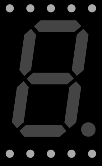
A Seven Segment Display is an electronic display device used to show decimal numerals and, in some cases, letters. It comprises seven individual Light Emitting Diodes (LEDs) arranged in a specific pattern, which when lit in various combinations, can represent numbers 0-9 and some letters. This Wokwi Compatible Seven Segment Display is designed to work seamlessly with the Wokwi simulation tool, allowing users to design, test, and visualize circuits before physical assembly.
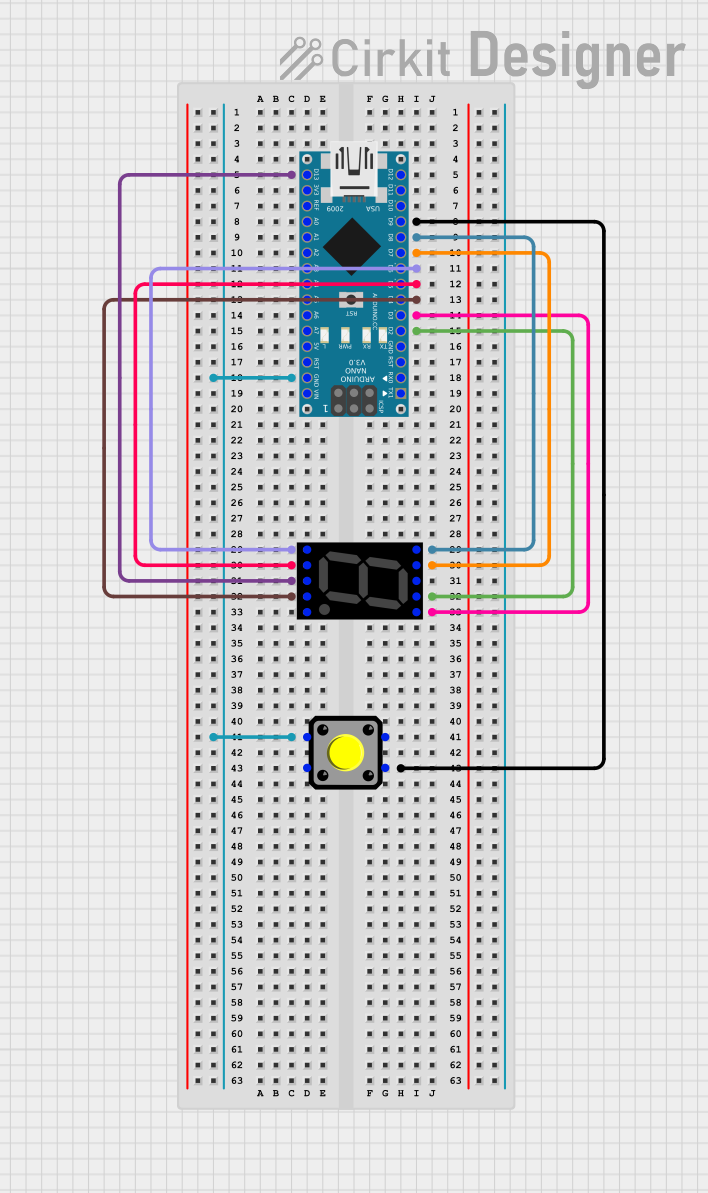
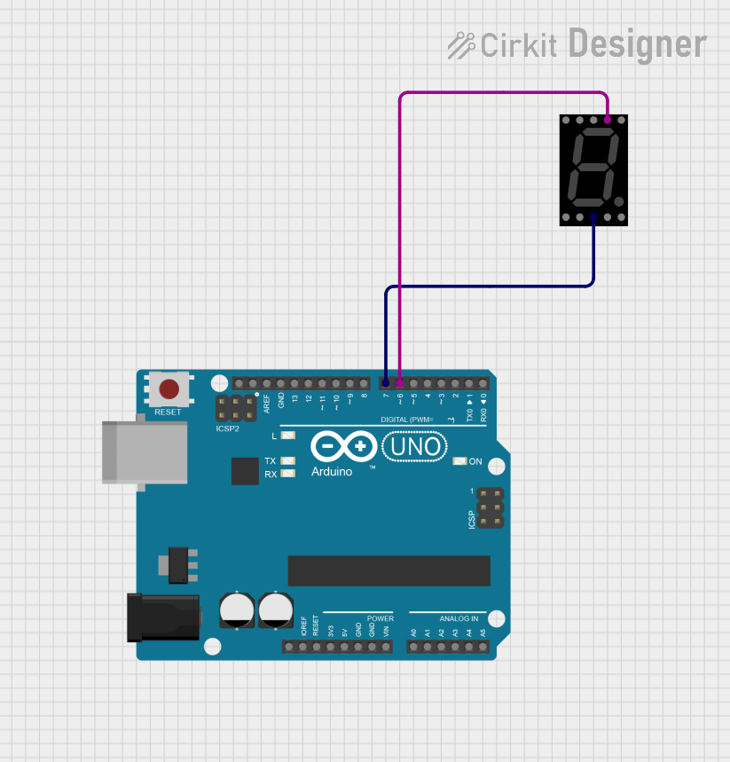
Explore Projects Built with Seven Segment Display (Wokwi Compatible)

 Open Project in Cirkit Designer
 Open Project in Cirkit Designer
 Open Project in Cirkit Designer
 Open Project in Cirkit Designer
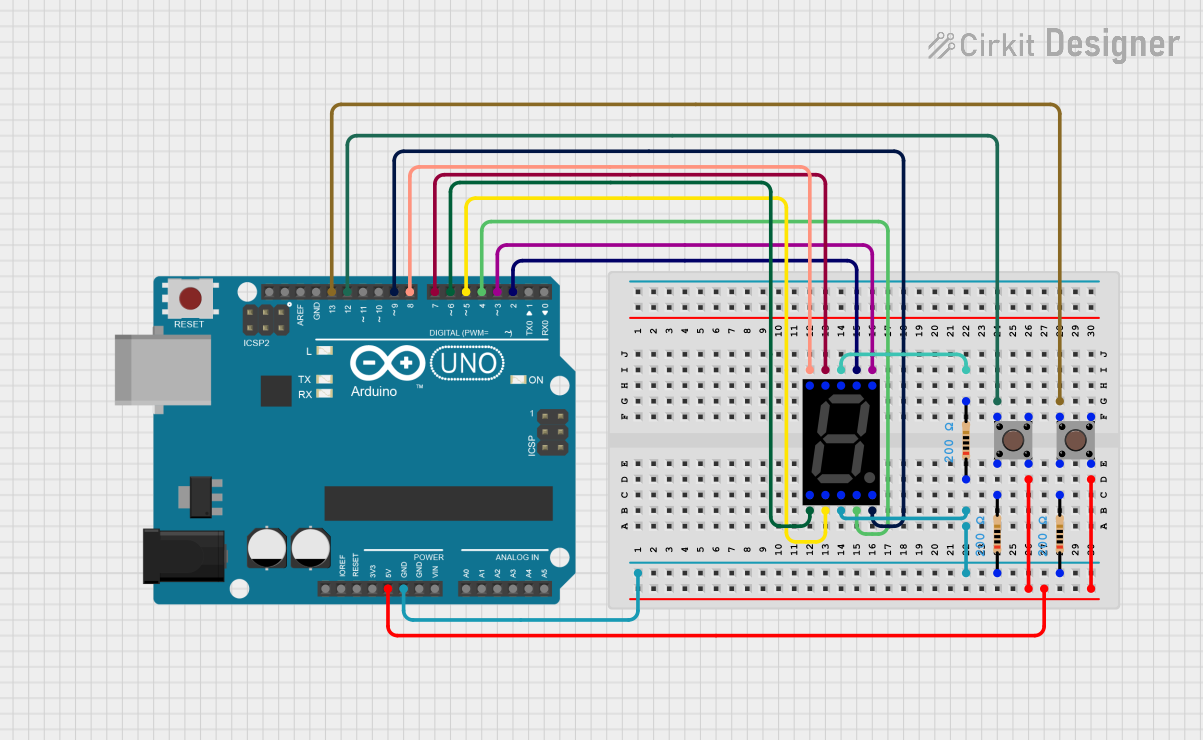
Explore Projects Built with Seven Segment Display (Wokwi Compatible)

 Open Project in Cirkit Designer
 Open Project in Cirkit Designer
 Open Project in Cirkit Designer
 Open Project in Cirkit Designer
Common Applications and Use Cases
- Digital clocks and timers
- Electronic meters
- Scoreboards
- Price display boards
- Basic calculators
Technical Specifications
Key Technical Details
- Operating Voltage: Typically 2.0V to 5.5V
- Forward Current (per segment): 10mA to 20mA
- Power Dissipation: Varies with model, often around 100mW
Pin Configuration and Descriptions
| Pin Number | Function | Description |
|---|---|---|
| 1 | Segment E | Controls the bottom left LED segment |
| 2 | Segment D | Controls the bottom LED segment |
| 3 | Common Cathode | Ground connection for common cathode type |
| 4 | Segment C | Controls the bottom right LED segment |
| 5 | Segment DP | Controls the decimal point LED segment |
| 6 | Segment B | Controls the top right LED segment |
| 7 | Segment A | Controls the top LED segment |
| 8 | Common Anode | Vcc connection for common anode type |
| 9 | Segment F | Controls the top left LED segment |
| 10 | Segment G | Controls the middle LED segment |
Usage Instructions
How to Use the Component in a Circuit
- Identify if the display is common anode or common cathode.
- Connect the common pins (3 and 8) to ground or Vcc, respectively.
- Use current-limiting resistors (typically 220-330 ohms) on each segment pin to prevent LED damage.
- Apply logic high or low to the segment pins to display the desired numeral or letter.
Important Considerations and Best Practices
- Always use current-limiting resistors to avoid burning out the LEDs.
- Check the datasheet for the exact forward voltage and current specifications.
- When interfacing with microcontrollers, ensure that the I/O pins can source or sink sufficient current.
Example Code for Arduino UNO
// Define the segment pins for the display
int segmentPins[] = {2, 3, 4, 5, 6, 7, 8, 9}; // A, B, C, D, E, F, G, DP

void setup() {
  // Set all the segment pins as output
  for (int i = 0; i < 8; i++) {
    pinMode(segmentPins[i], OUTPUT);
  }
}

void loop() {
  // Display the number '0'
  int number0[] = {HIGH, HIGH, HIGH, HIGH, HIGH, HIGH, LOW, LOW}; // A-G, DP
  displayNumber(number0);
  delay(1000); // Wait for 1 second
}

// Function to display a number on the seven-segment display
void displayNumber(int number[]) {
  for (int segment = 0; segment < 8; segment++) {
    digitalWrite(segmentPins[segment], number[segment]);
  }
}
Troubleshooting and FAQs
Common Issues Users Might Face
- Segments not lighting up: Check the connections and ensure that the common pin is correctly connected to either Vcc or ground, depending on the type of display.
- Dim segments: Ensure that the current-limiting resistors are of the correct value and that the power supply is adequate.
- Incorrect numbers displayed: Verify the logic levels applied to the segment pins and the order of the pin connections.
Solutions and Tips for Troubleshooting
- Double-check wiring against the pin configuration table.
- Measure the voltage across each segment to ensure it falls within the operating range.
- Replace current-limiting resistors if they do not match the recommended values.
FAQs
Q: Can I use a Seven Segment Display without resistors? A: It is not recommended as it may lead to excessive current through the LEDs, potentially damaging them.
Q: How can I display letters on the Seven Segment Display? A: Some letters can be displayed by lighting up the appropriate segments. For example, to display the letter "A," light up segments A, B, C, E, F, and G.
Q: Can I control a Seven Segment Display with a 3.3V microcontroller? A: Yes, but ensure that the forward voltage of the segments is compatible with 3.3V, and adjust the current-limiting resistors accordingly.