How to Use LDR: Examples, Pinouts, and Specs
Introduction
A Light Dependent Resistor (LDR), also known as a photoresistor, is a passive electronic component whose resistance changes based on the intensity of light it is exposed to. The resistance of an LDR decreases with increasing incident light intensity; conversely, it increases as the light intensity decreases. This characteristic makes LDRs suitable for light sensing applications, such as light meters, clock radios, night lights, outdoor clocks, and security systems.
Explore Projects Built with LDR
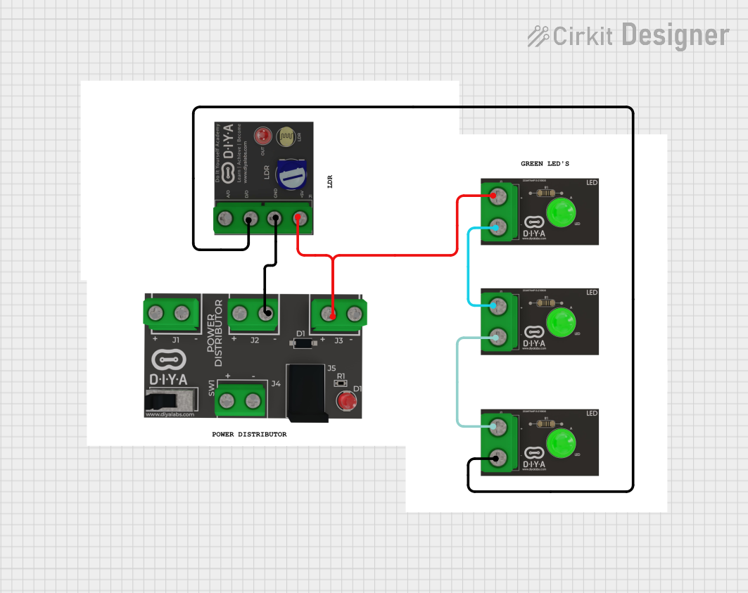
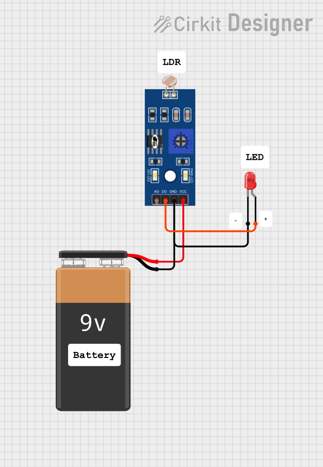
Explore Projects Built with LDR
Technical Specifications
Key Technical Details
- Resistance Range: Typically 1 MΩ (dark) to a few hundred ohms (bright light)
- Power Rating: Generally around 150 mW
- Maximum Voltage: Dependent on the specific model, often around 150V
- Spectral Peak: Typically around 560 nm (green visible light)
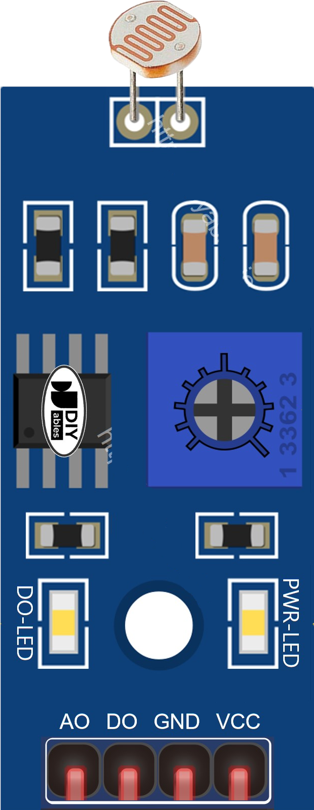
Pin Configuration and Descriptions
LDRs are two-terminal devices and do not have a polarity, meaning they can be connected in any direction in a circuit.
| Pin | Description |
|---|---|
| 1 | Photoresistive layer (can be connected to Vcc) |
| 2 | Conductive substrate (can be connected to ground) |
Usage Instructions
How to Use the LDR in a Circuit
To use an LDR in a circuit, it is commonly placed in series with a resistor to form a voltage divider. This setup allows the measurement of voltage changes across the LDR as the light intensity varies.
Example Circuit
Vcc ----/\/\/\-----| LDR |----- GND
          R1        Photoresistor
In this circuit, R1 is a fixed resistor, and the LDR is the photoresistor. The voltage at the junction between R1 and the LDR can be measured and will vary with light intensity.
Important Considerations and Best Practices
- Avoid Excessive Voltage: Applying a voltage higher than the maximum rating can damage the LDR.
- Shield from High-Temperature Sources: High temperatures can permanently affect the resistance of the LDR.
- Calibration: Since LDRs can vary significantly from one to another, calibration is recommended for precise applications.
- Response Time: LDRs have a slow response time compared to photodiodes or phototransistors, so they are not suitable for applications requiring quick light changes detection.
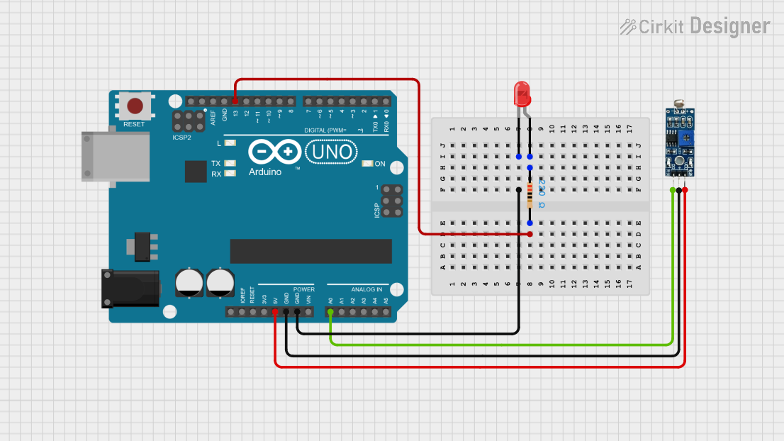
Example Arduino UNO Code
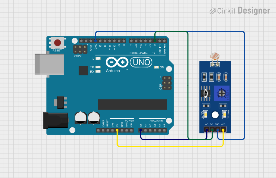
The following example demonstrates how to use an LDR with an Arduino UNO to measure light intensity.
int ldrPin = A0; // LDR connected to analog pin A0
int ldrValue = 0; // Variable to store LDR value

void setup() {
  Serial.begin(9600); // Start serial communication at 9600 baud
}

void loop() {
  ldrValue = analogRead(ldrPin); // Read the value from the LDR
  Serial.println(ldrValue); // Print the LDR value to the serial monitor
  delay(500); // Wait for half a second before reading again
}
In this code, the LDR is connected to the analog pin A0 of the Arduino. The analogRead function reads the voltage across the LDR, which is then printed to the serial monitor.
Troubleshooting and FAQs
Common Issues
- Inconsistent Readings: Ensure that the LDR is not exposed to fluctuating light sources and that connections are secure.
- No Change in Resistance: Check if the LDR is damaged or if the light intensity is not varying significantly.
Solutions and Tips for Troubleshooting
- Check Connections: Verify that all connections are correct and secure.
- Test with a Multimeter: Use a multimeter to check the resistance of the LDR in different lighting conditions to ensure it is functioning correctly.
- Replace the LDR: If the LDR does not respond to light changes, it may be faulty and need replacement.
FAQs
Q: Can I use an LDR to measure the exact intensity of light? A: LDRs are not precision devices and are best suited for detecting changes in light levels rather than measuring exact intensities.
Q: How do I choose the value of the fixed resistor in the voltage divider? A: The fixed resistor value (R1) should be chosen based on the expected range of light levels. A common approach is to select R1 to be approximately equal to the resistance of the LDR at the midpoint of the expected light range.
Q: Are LDRs sensitive to all types of light? A: LDRs are most sensitive to visible light, with peak sensitivity typically around green light (560 nm). Their sensitivity decreases for wavelengths outside of the visible spectrum.