How to Use AC DIGITAL VOLTMETER AMMETER: Examples, Pinouts, and Specs
Introduction
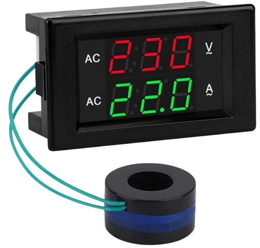
The AC Digital Voltmeter Ammeter is a multifunctional electronic component designed to measure both voltage and current in AC circuits. It is widely used in electrical systems to monitor power consumption, ensure safety, and diagnose issues. This component typically features a digital display for real-time readings, making it user-friendly and highly practical for various applications.
Explore Projects Built with AC DIGITAL VOLTMETER AMMETER
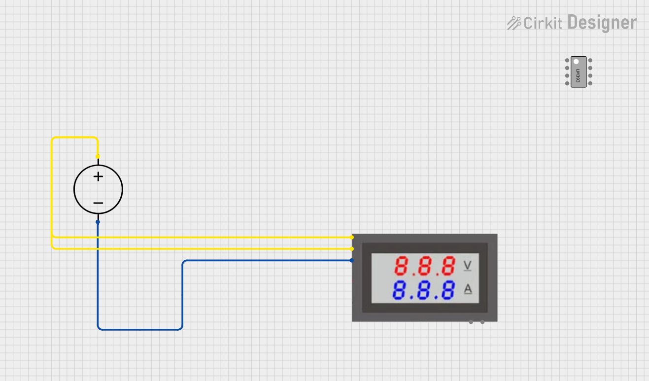
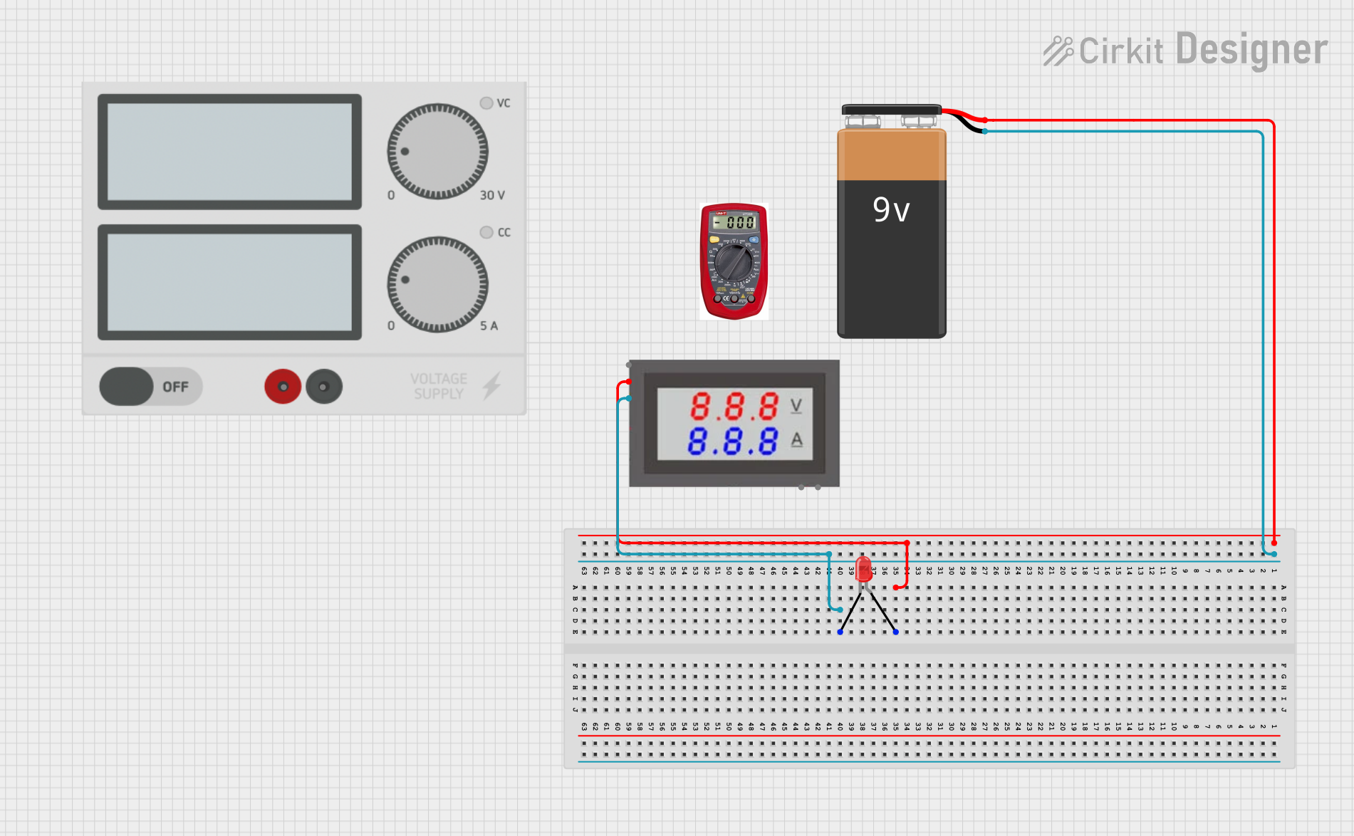
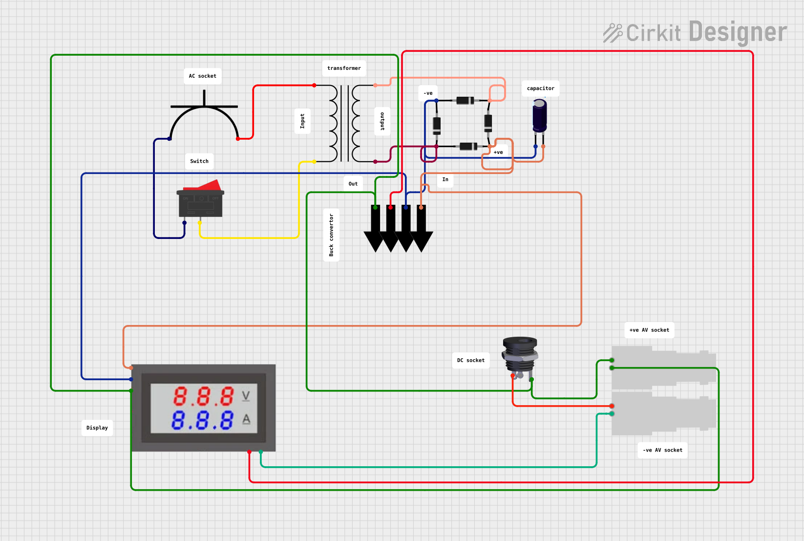

Explore Projects Built with AC DIGITAL VOLTMETER AMMETER
Common Applications and Use Cases
- Monitoring voltage and current in household or industrial AC circuits.
- Measuring power consumption in appliances and devices.
- Troubleshooting electrical systems.
- Integrating into DIY projects for real-time AC parameter monitoring.
Technical Specifications
Below are the key technical details of a typical AC Digital Voltmeter Ammeter:
| Parameter | Specification |
|---|---|
| Voltage Measurement Range | 80V AC to 300V AC |
| Current Measurement Range | 0A to 100A (with external current transformer) |
| Display Type | LED (dual display for voltage and current) |
| Accuracy | ±1% |
| Power Supply | Self-powered (from measured AC line) |
| Operating Temperature | -10°C to 50°C |
| Dimensions | Varies by model (e.g., 70mm x 40mm x 30mm) |
Pin Configuration and Descriptions
The AC Digital Voltmeter Ammeter typically has the following connections:
| Pin/Terminal | Description |
|---|---|
| Voltage Input (V) | Connects to the AC line for voltage measurement. |
| Neutral (N) | Connects to the neutral line of the AC circuit. |
| Current Transformer (CT) | Connects to the external current transformer for current measurement. |
Usage Instructions
How to Use the Component in a Circuit
Connect the Voltage Input (V):
Attach the voltage input terminal to the live wire of the AC circuit. Ensure the connection is secure and insulated to prevent electrical hazards.Connect the Neutral (N):
Connect the neutral terminal to the neutral wire of the AC circuit.Install the Current Transformer (CT):
- Place the current transformer around the live wire of the AC circuit.
- Connect the CT's output wires to the corresponding terminals on the voltmeter ammeter. Ensure the polarity is correct (check the markings on the CT and the meter).
Power On the Circuit:
Once all connections are made, power on the AC circuit. The digital display will show the voltage and current readings in real time.
Important Considerations and Best Practices
- Safety First: Always ensure the circuit is powered off before making any connections. Use insulated tools and wear protective gear.
- Current Transformer Placement: The CT must only enclose the live wire, not both live and neutral wires, to measure current accurately.
- Voltage Range: Ensure the measured voltage does not exceed the specified range (e.g., 300V AC) to avoid damage to the device.
- Secure Mounting: Mount the voltmeter ammeter securely to prevent vibrations or accidental disconnections.
Arduino UNO Integration
While the AC Digital Voltmeter Ammeter is typically a standalone device, you can integrate it with an Arduino UNO for additional functionality, such as data logging or remote monitoring. Below is an example of how to read data from the device using an analog input (if the device provides an analog output for voltage or current):
// Example code to read voltage and current from an analog output
// of the AC Digital Voltmeter Ammeter using Arduino UNO

const int voltagePin = A0; // Analog pin connected to voltage output
const int currentPin = A1; // Analog pin connected to current output

void setup() {
  Serial.begin(9600); // Initialize serial communication
}

void loop() {
  // Read analog values from the voltmeter ammeter
  int voltageValue = analogRead(voltagePin);
  int currentValue = analogRead(currentPin);

  // Convert analog values to actual voltage and current
  // Assuming a 10-bit ADC and a scaling factor for the device
  float voltage = (voltageValue / 1023.0) * 300.0; // Scale to 0-300V
  float current = (currentValue / 1023.0) * 100.0; // Scale to 0-100A

  // Print the readings to the Serial Monitor
  Serial.print("Voltage: ");
  Serial.print(voltage);
  Serial.println(" V");

  Serial.print("Current: ");
  Serial.print(current);
  Serial.println(" A");

  delay(1000); // Wait for 1 second before the next reading
}
Troubleshooting and FAQs
Common Issues and Solutions
No Display or Readings:
- Cause: Incorrect wiring or no power supply.
- Solution: Double-check all connections, especially the voltage input and neutral terminals. Ensure the circuit is powered.
Inaccurate Current Readings:
- Cause: Incorrect placement of the current transformer.
- Solution: Ensure the CT is placed around the live wire only and not both live and neutral wires.
Flickering Display:
- Cause: Unstable AC supply or loose connections.
- Solution: Check the AC supply for stability and tighten all connections.
Overload or Damage:
- Cause: Voltage or current exceeds the specified range.
- Solution: Use the device within its rated specifications. Add protective components like fuses if necessary.
FAQs
Q: Can this device measure DC voltage or current?
A: No, this device is designed specifically for AC circuits and cannot measure DC parameters.
Q: Is the current transformer included with the device?
A: Most models include a current transformer, but it is recommended to verify this with the seller or manufacturer.
Q: Can I use this device for three-phase systems?
A: This device is typically designed for single-phase systems. For three-phase systems, you will need a specialized meter.
Q: How do I calibrate the device?
A: Most models are factory-calibrated and do not require user calibration. If calibration is needed, refer to the manufacturer's instructions.
By following this documentation, you can effectively use the AC Digital Voltmeter Ammeter for your projects and applications.