How to Use TIP122: Examples, Pinouts, and Specs
Introduction
The TIP122 is an NPN Darlington transistor designed for switching and amplification applications. It features a high current gain and can handle significant current and voltage, making it ideal for driving motors, solenoids, and other high-power devices. Its robust design and ease of use make it a popular choice in both hobbyist and industrial projects.
Explore Projects Built with TIP122
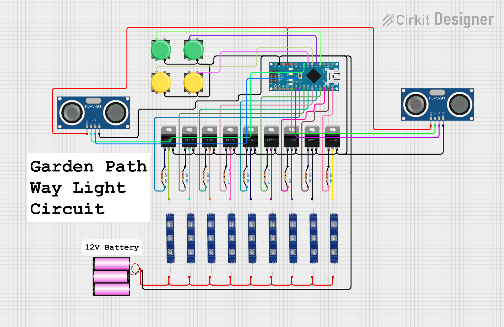
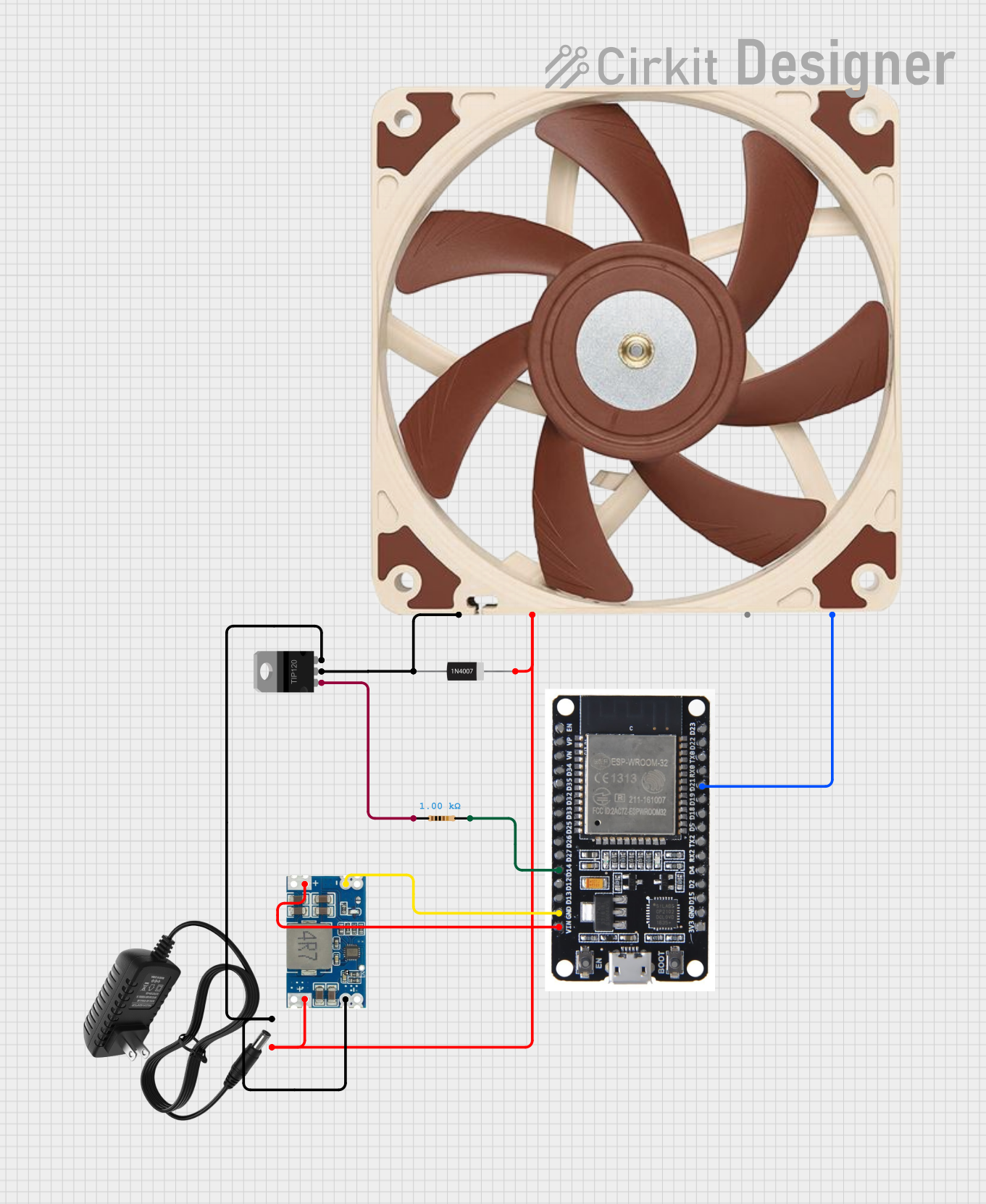
Explore Projects Built with TIP122
Common Applications
- Motor control circuits
- LED and lamp driving
- Solenoid control
- Audio amplification
- General-purpose high-power switching
Technical Specifications
The TIP122 is a high-power transistor with the following key specifications:
| Parameter | Value |
|---|---|
| Transistor Type | NPN Darlington |
| Maximum Collector-Emitter Voltage (VCEO) | 100V |
| Maximum Collector-Base Voltage (VCBO) | 100V |
| Maximum Emitter-Base Voltage (VEBO) | 5V |
| Maximum Collector Current (IC) | 5A |
| Maximum Power Dissipation (PD) | 65W |
| DC Current Gain (hFE) | 1000 (minimum) |
| Operating Temperature Range | -65°C to +150°C |
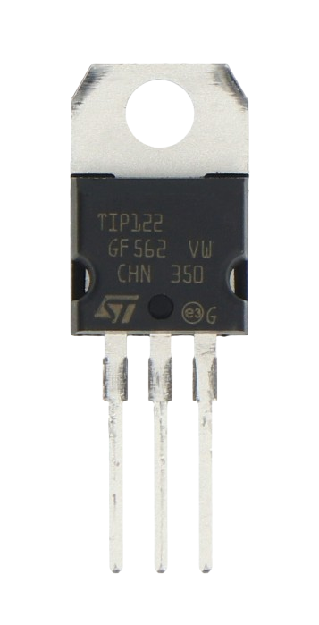
| Package Type | TO-220 |
Pin Configuration
The TIP122 has three pins, as shown below:
| Pin Number | Pin Name | Description |
|---|---|---|
| 1 | Base (B) | Controls the transistor's operation |
| 2 | Collector (C) | Current flows into this pin |
| 3 | Emitter (E) | Current flows out of this pin |
The pinout of the TIP122 in the TO-220 package is as follows (viewed from the front, with the pins facing downward):
- Base
- Collector
- Emitter
Usage Instructions
The TIP122 is straightforward to use in circuits for switching or amplification. Below are the steps and considerations for using the TIP122 effectively:
Using the TIP122 in a Circuit
- Base Resistor: Always use a resistor between the base pin and the control signal (e.g., from a microcontroller or other logic circuit). This limits the base current and prevents damage to the transistor. A typical value is 1kΩ, but it depends on the control voltage and desired collector current.
- Load Connection: Connect the load (e.g., motor, LED, or solenoid) between the positive voltage supply and the collector pin.
- Emitter Connection: Connect the emitter pin to ground.
- Control Signal: Apply a control signal to the base pin to turn the transistor on or off. When the base is driven high, the transistor allows current to flow from the collector to the emitter, powering the load.
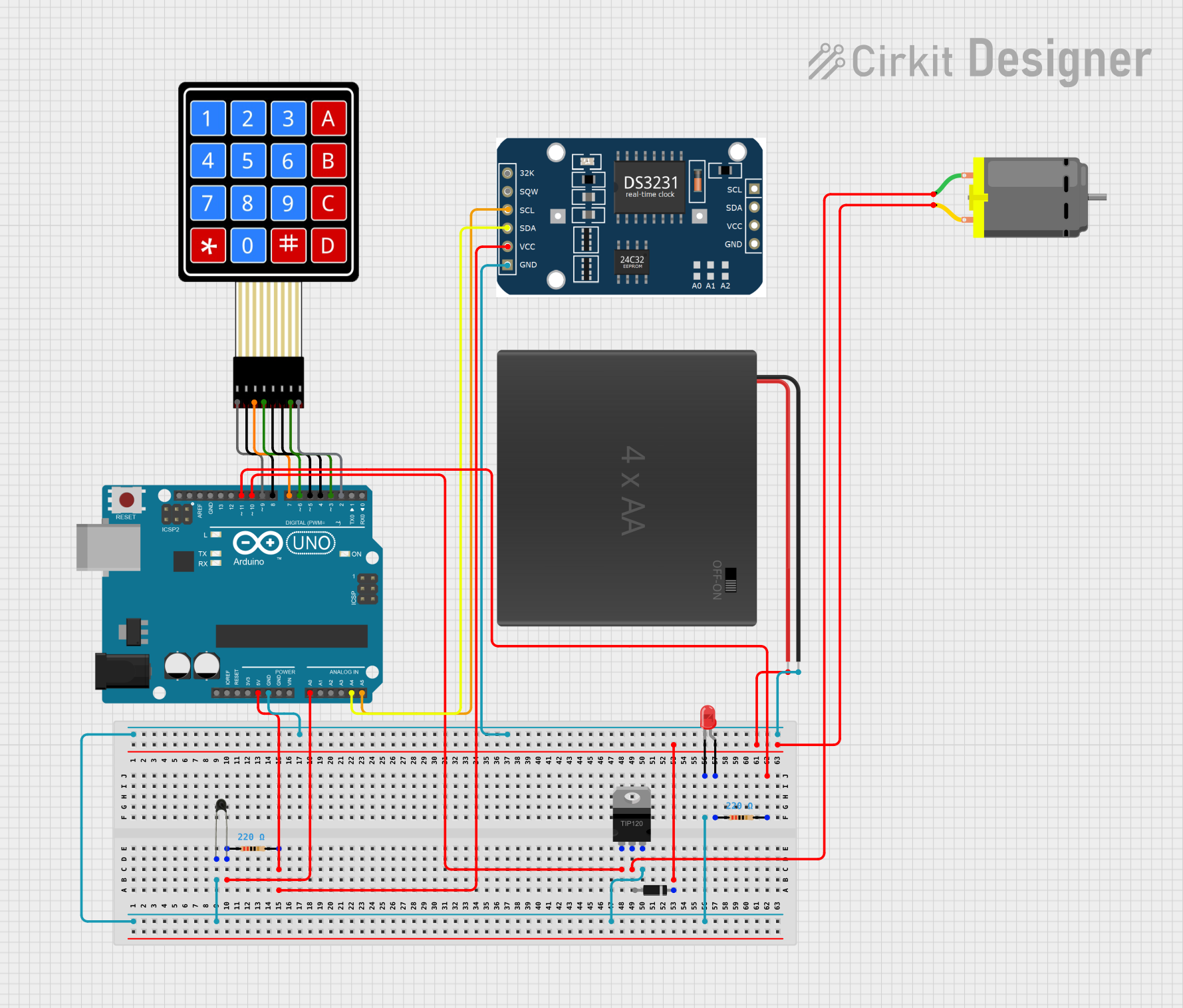
Example Circuit with Arduino UNO
The following example demonstrates how to use the TIP122 to control a DC motor with an Arduino UNO:
Circuit Diagram
- Connect the motor between the positive voltage supply (e.g., 12V) and the collector pin of the TIP122.
- Connect the emitter pin to ground.
- Use a 1kΩ resistor between the Arduino's digital pin and the base pin of the TIP122.
- Add a flyback diode (e.g., 1N4007) across the motor terminals to protect the transistor from voltage spikes.
Arduino Code
// TIP122 Example: Controlling a DC motor with Arduino UNO
// Connect the TIP122 base to pin 9 via a 1kΩ resistor
// Connect the motor between the 12V supply and the TIP122 collector
// Don't forget to add a flyback diode across the motor terminals

const int motorPin = 9; // Arduino pin connected to TIP122 base

void setup() {
  pinMode(motorPin, OUTPUT); // Set motorPin as an output
}

void loop() {
  digitalWrite(motorPin, HIGH); // Turn the motor ON
  delay(2000);                  // Keep it ON for 2 seconds
  digitalWrite(motorPin, LOW);  // Turn the motor OFF
  delay(2000);                  // Keep it OFF for 2 seconds
}
Important Considerations
- Heat Dissipation: The TIP122 can dissipate up to 65W of power. Use a heatsink if the transistor is expected to handle high currents for extended periods.
- Flyback Diode: When driving inductive loads (e.g., motors or solenoids), always use a flyback diode to protect the transistor from voltage spikes.
- Base Current: Ensure the base current is sufficient to fully saturate the transistor. For high currents, calculate the required base current using the formula:
I_B = I_C / h_FE
whereI_Cis the collector current andh_FEis the current gain.
Troubleshooting and FAQs
Common Issues
Transistor Overheating
- Cause: Excessive current or insufficient heat dissipation.
- Solution: Use a heatsink and ensure the load current does not exceed 5A.
Load Not Turning On
- Cause: Insufficient base current or incorrect wiring.
- Solution: Check the base resistor value and ensure proper connections.
Voltage Spikes Damaging the Transistor
- Cause: Inductive loads generating back EMF.
- Solution: Add a flyback diode across the load.
Transistor Always On or Off
- Cause: Faulty transistor or incorrect control signal.
- Solution: Test the transistor with a multimeter and verify the control signal.
FAQs
Can the TIP122 be used with 3.3V logic?
Yes, but ensure the base resistor is appropriately chosen to provide sufficient base current.What is the maximum load voltage the TIP122 can handle?
The TIP122 can handle up to 100V across the collector-emitter terminals.Can the TIP122 drive a stepper motor?
Yes, but you will need additional circuitry (e.g., a stepper motor driver) to control the motor phases.Is the TIP122 suitable for audio amplification?
Yes, the TIP122 can be used in audio amplification circuits, though it is more commonly used for switching applications.
By following these guidelines and best practices, you can effectively use the TIP122 in your projects.