
How to Use IchigoJam T: Examples, Pinouts, and Specs
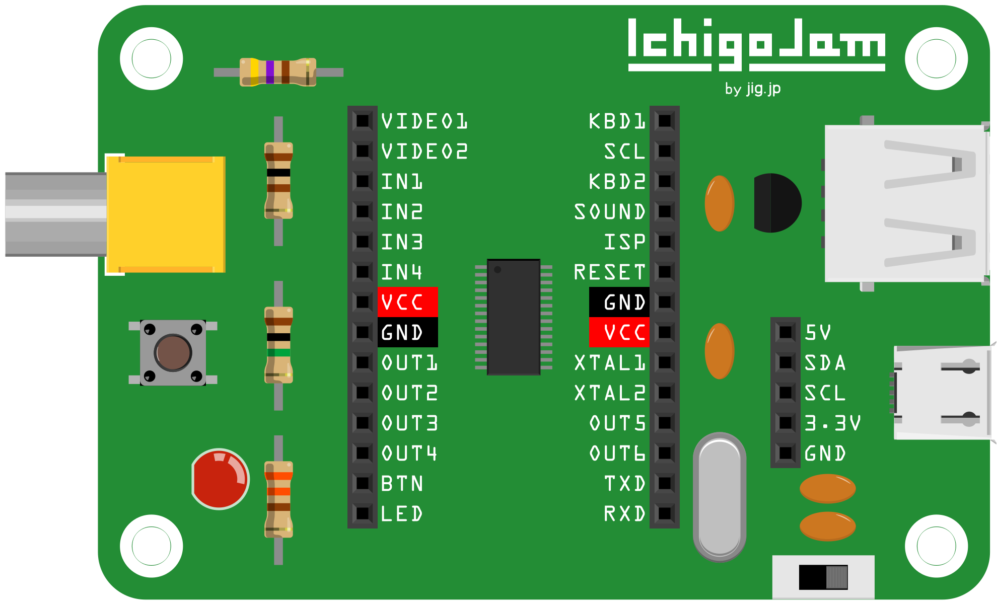
 Design with IchigoJam T in Cirkit Designer
Introduction
The IchigoJam T is a compact, educational microcomputer designed to introduce beginners to programming and electronics. It features a built-in BASIC programming language, making it easy to write and execute code directly on the device. With its simple interface and support for various input/output devices, the IchigoJam T is an excellent tool for teaching coding concepts, hardware interaction, and prototyping small projects.
Explore Projects Built with IchigoJam T
 Open Project in Cirkit Designer
 Open Project in Cirkit Designer
 Open Project in Cirkit Designer
 Open Project in Cirkit Designer
Explore Projects Built with IchigoJam T
Open Project in Cirkit DesignerOpen Project in Cirkit DesignerOpen Project in Cirkit DesignerOpen Project in Cirkit DesignerCommon Applications and Use Cases
- Teaching programming fundamentals to students and beginners
- Prototyping simple electronic circuits and projects
- Controlling external devices such as LEDs, sensors, and motors
- Building interactive educational tools and games
- Learning hardware-software integration in a hands-on manner
Technical Specifications
The IchigoJam T is designed to be user-friendly while offering sufficient functionality for educational and prototyping purposes. Below are its key technical specifications:
| Specification | Details |
|---|---|
| Processor | NXP LPC1114 ARM Cortex-M0 (50 MHz) |
| Memory | 32 KB Flash, 4 KB RAM |
| Power Supply | 5V DC (via USB or external power source) |
| Input/Output Pins | 11 GPIO pins (digital and analog support) |
| Video Output | Composite video (NTSC) |
| Keyboard Input | PS/2 keyboard support |
| Programming Language | Built-in BASIC interpreter |
| Dimensions | 50 mm x 50 mm |
Pin Configuration and Descriptions
The IchigoJam T features a simple pin layout for connecting external devices. Below is the pin configuration:
| Pin | Name | Description |
|---|---|---|
| 1 | VCC | Power supply input (5V) |
| 2 | GND | Ground |
| 3 | P0 | General-purpose I/O (GPIO) pin |
| 4 | P1 | General-purpose I/O (GPIO) pin |
| 5 | P2 | General-purpose I/O (GPIO) pin |
| 6 | P3 | General-purpose I/O (GPIO) pin |
| 7 | P4 | General-purpose I/O (GPIO) pin |
| 8 | P5 | General-purpose I/O (GPIO) pin |
| 9 | P6 | General-purpose I/O (GPIO) pin |
| 10 | P7 | General-purpose I/O (GPIO) pin |
| 11 | P8 | General-purpose I/O (GPIO) pin |
| 12 | P9 | General-purpose I/O (GPIO) pin |
Usage Instructions
The IchigoJam T is straightforward to use, making it ideal for beginners. Follow the steps below to get started:
Setting Up the IchigoJam T
- Power the Device: Connect the IchigoJam T to a 5V power source using a USB cable or an external power supply.
- Connect a Display: Use the composite video output to connect the IchigoJam T to a monitor or TV.
- Attach a Keyboard: Plug a PS/2 keyboard into the keyboard input port for programming and interaction.
Writing and Running Code
The IchigoJam T uses a built-in BASIC interpreter. Here's an example of a simple program to blink an LED connected to pin P0:
10 OUT 0,1  ' Turn on the LED connected to pin P0
20 WAIT 30  ' Wait for 0.3 seconds
30 OUT 0,0  ' Turn off the LED connected to pin P0
40 WAIT 30  ' Wait for 0.3 seconds
50 GOTO 10  ' Repeat the loop
Connecting to External Devices
- LEDs: Connect the anode (longer leg) of the LED to a GPIO pin (e.g., P0) and the cathode (shorter leg) to a resistor, then to GND.
- Sensors: Use analog or digital GPIO pins to read sensor data.
- Motors: Use a motor driver circuit to control motors via GPIO pins.
Best Practices
- Always use resistors with LEDs to prevent damage.
- Avoid exceeding the maximum current rating of GPIO pins (typically 4 mA per pin).
- Use external pull-up or pull-down resistors for stable input readings.
Troubleshooting and FAQs
Common Issues and Solutions
No Display Output
- Ensure the composite video cable is securely connected to the monitor and the IchigoJam T.
- Verify that the monitor is set to the correct input source (NTSC).
Keyboard Not Working
- Check if the PS/2 keyboard is properly connected.
- Use a compatible PS/2 keyboard, as USB keyboards with adapters may not work.
Program Not Running
- Ensure the program is written in valid BASIC syntax.
- Use the
LISTcommand to review the program and check for errors.
GPIO Pins Not Responding
- Verify the connections to external devices.
- Check if the pin mode is correctly configured in the program.
FAQs
Q: Can I power the IchigoJam T with batteries?
A: Yes, you can use a 5V battery pack or a regulated power supply to power the device.
Q: Is it possible to save programs on the IchigoJam T?
A: Yes, you can save programs to the device's memory using the SAVE command and load them later with the LOAD command.
Q: Can I connect the IchigoJam T to an Arduino?
A: Yes, you can interface the IchigoJam T with an Arduino using GPIO pins for communication.
By following this documentation, you can effectively use the IchigoJam T for learning, teaching, and prototyping projects.