How to Use 16 Pin IC Socket: Examples, Pinouts, and Specs

 Design with 16 Pin IC Socket in Cirkit Designer
Introduction
A 16-pin IC socket is a holder for integrated circuits (ICs) with 16 pins. It provides a removable interface to the IC, protecting it from heat during soldering and allowing for easy replacement or upgrading of the IC. This component is essential in prototyping and development environments where ICs may need to be frequently swapped or replaced.
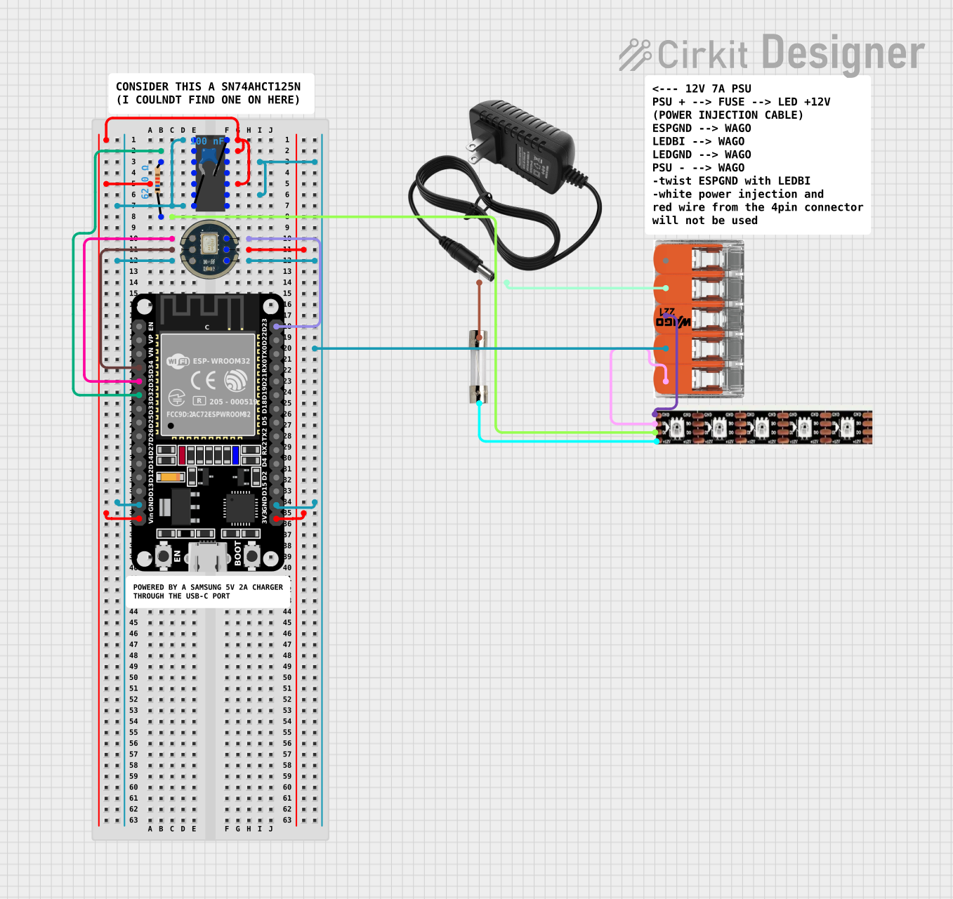
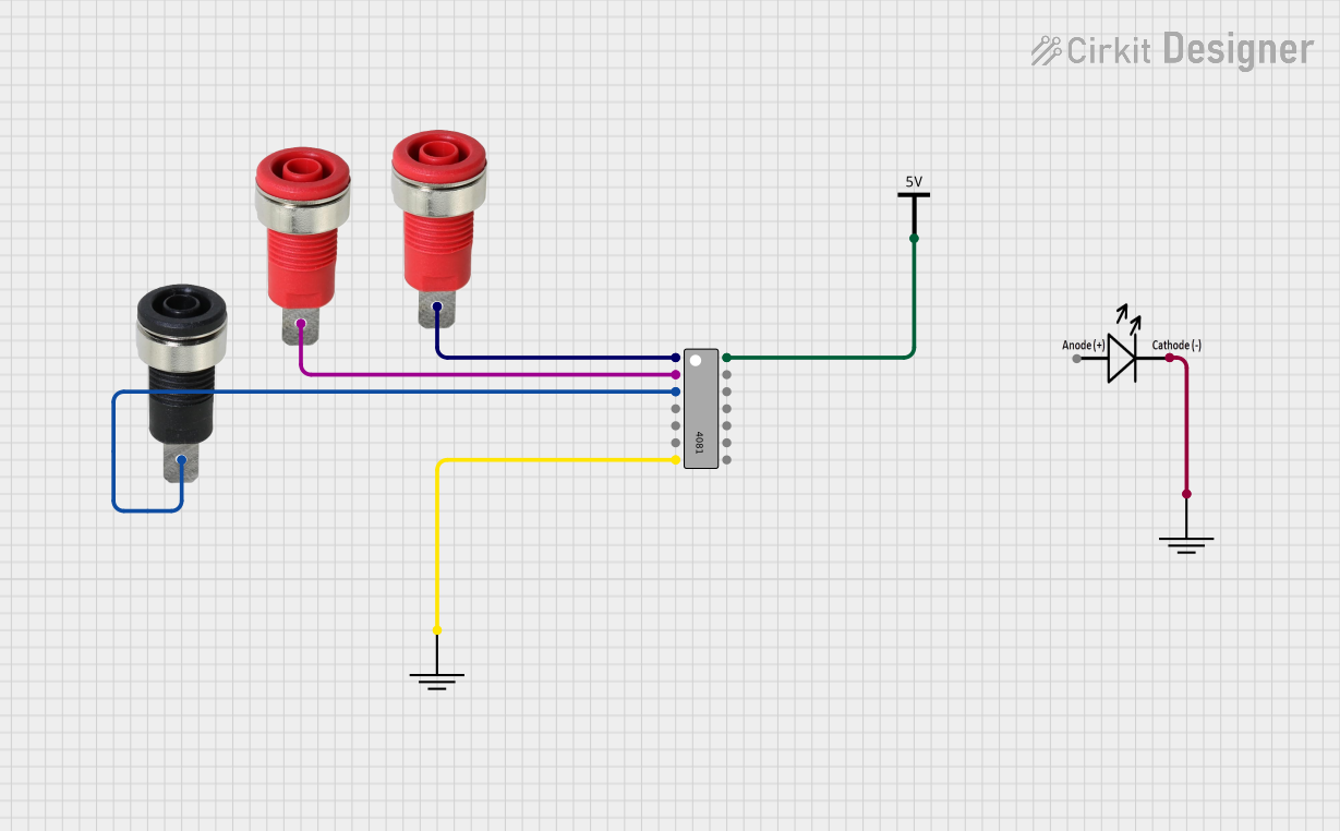
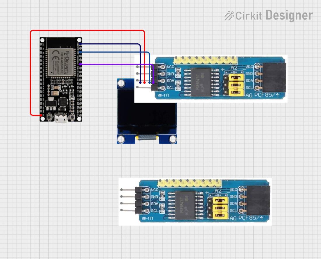
Explore Projects Built with 16 Pin IC Socket

 Open Project in Cirkit Designer
 Open Project in Cirkit Designer
 Open Project in Cirkit Designer
 Open Project in Cirkit Designer
Explore Projects Built with 16 Pin IC Socket

 Open Project in Cirkit Designer
 Open Project in Cirkit Designer
 Open Project in Cirkit Designer
 Open Project in Cirkit Designer
Common Applications and Use Cases
- Prototyping and Development: Allows for easy replacement of ICs without desoldering.
- Circuit Protection: Protects ICs from heat damage during soldering.
- Upgradability: Facilitates easy upgrades of ICs in a circuit.
- Testing and Debugging: Simplifies the process of testing and debugging circuits by allowing quick IC swaps.
Technical Specifications
Key Technical Details
| Specification | Value |
|---|---|
| Manufacturer | Anyone |
| Part ID | 16 |
| Number of Pins | 16 |
| Pin Pitch | 2.54 mm (0.1 inches) |
| Material | Plastic body, metal contacts |
| Operating Temperature Range | -55°C to +125°C |
| Contact Resistance | < 20 mΩ |
| Insulation Resistance | > 1000 MΩ |
Pin Configuration and Descriptions
| Pin Number | Description |
|---|---|
| 1 | IC Pin 1 |
| 2 | IC Pin 2 |
| 3 | IC Pin 3 |
| 4 | IC Pin 4 |
| 5 | IC Pin 5 |
| 6 | IC Pin 6 |
| 7 | IC Pin 7 |
| 8 | IC Pin 8 |
| 9 | IC Pin 9 |
| 10 | IC Pin 10 |
| 11 | IC Pin 11 |
| 12 | IC Pin 12 |
| 13 | IC Pin 13 |
| 14 | IC Pin 14 |
| 15 | IC Pin 15 |
| 16 | IC Pin 16 |
Usage Instructions
How to Use the Component in a Circuit
- Insert the IC Socket: Place the 16-pin IC socket on the PCB where the IC is intended to be mounted. Ensure that the orientation notch on the socket matches the orientation on the PCB.
- Solder the Socket: Solder each pin of the socket to the corresponding pad on the PCB. Ensure that the solder joints are clean and free of bridges.
- Insert the IC: Carefully align the IC pins with the socket holes and press the IC into the socket. Ensure that the IC is fully seated and that all pins are correctly inserted.
Important Considerations and Best Practices
- Orientation: Always check the orientation of the IC and the socket to avoid incorrect connections.
- Soldering: Use a low-temperature soldering iron to avoid damaging the socket or the PCB.
- Handling: Handle the IC and socket with care to avoid bending the pins.
- Testing: After inserting the IC, test the circuit to ensure proper functionality before proceeding with further assembly.
Troubleshooting and FAQs
Common Issues Users Might Face
IC Not Functioning:
- Solution: Check the orientation of the IC and ensure it is correctly seated in the socket. Verify that all pins are making good contact.
Intermittent Connections:
- Solution: Inspect the solder joints for cold solder joints or bridges. Re-solder if necessary.
Bent Pins:
- Solution: Carefully straighten the pins using a pair of needle-nose pliers before inserting the IC into the socket.
FAQs
Q: Can I use a 16-pin IC socket for an IC with fewer than 16 pins? A: Yes, you can use a 16-pin IC socket for ICs with fewer pins, but ensure that the unused pins do not interfere with the circuit.
Q: How do I remove an IC from the socket without damaging it? A: Use an IC extraction tool or a small flathead screwdriver to gently pry the IC out of the socket, working from both ends to avoid bending the pins.
Q: Can I reuse a 16-pin IC socket? A: Yes, IC sockets are designed to be reusable. However, ensure that the socket and the IC pins are not damaged during removal and reinsertion.
Conclusion
The 16-pin IC socket is a versatile and essential component for anyone working with integrated circuits. By providing a removable interface, it simplifies the process of prototyping, testing, and upgrading circuits. With proper usage and handling, it can significantly enhance the efficiency and reliability of your electronic projects.