How to Use Motor Driver : Examples, Pinouts, and Specs
Introduction
The HS-F04A Motor Driver, manufactured by ESP32, is an electronic circuit designed to control the operation of motors by providing the necessary voltage and current. It enables precise control of motor speed and direction, making it an essential component in applications such as robotics, automation, and motorized systems. This motor driver is particularly well-suited for DC motors and stepper motors, offering reliable performance and ease of integration into various projects.
Explore Projects Built with Motor Driver


Explore Projects Built with Motor Driver
Common Applications and Use Cases
- Robotics: Controlling the movement of robotic arms, wheels, or tracks.
- Automation: Driving conveyor belts, automated doors, or industrial machinery.
- DIY Projects: Building motorized vehicles, drones, or home automation systems.
- Educational Projects: Teaching motor control concepts in electronics and programming.
Technical Specifications
The HS-F04A Motor Driver is designed to handle a wide range of motor control requirements. Below are its key technical details:
General Specifications
| Parameter | Value |
|---|---|
| Manufacturer | ESP32 |
| Part ID | HS-F04A |
| Operating Voltage | 5V to 12V |
| Maximum Output Current | 2A per channel |
| Number of Channels | 2 (supports dual motor control) |
| Motor Type Supported | DC motors, Stepper motors |
| Control Interface | PWM (Pulse Width Modulation) |
| Operating Temperature | -20°C to 85°C |
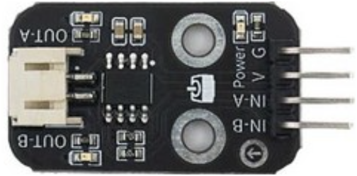
Pin Configuration and Descriptions
The HS-F04A Motor Driver features a simple pinout for easy integration into circuits. Below is the pin configuration:
| Pin Name | Pin Number | Description |
|---|---|---|
| VCC | 1 | Power supply input (5V to 12V). |
| GND | 2 | Ground connection. |
| IN1 | 3 | Input signal for controlling Motor 1 direction. |
| IN2 | 4 | Input signal for controlling Motor 1 direction. |
| IN3 | 5 | Input signal for controlling Motor 2 direction. |
| IN4 | 6 | Input signal for controlling Motor 2 direction. |
| ENA | 7 | Enable pin for Motor 1 (PWM input for speed control). |
| ENB | 8 | Enable pin for Motor 2 (PWM input for speed control). |
| OUT1 | 9 | Output terminal for Motor 1. |
| OUT2 | 10 | Output terminal for Motor 1. |
| OUT3 | 11 | Output terminal for Motor 2. |
| OUT4 | 12 | Output terminal for Motor 2. |
Usage Instructions
How to Use the Component in a Circuit
- Power Supply: Connect the VCC pin to a power source (5V to 12V) and the GND pin to the ground of your circuit.
- Motor Connections: Connect the motor terminals to the OUT1, OUT2 (for Motor 1) and OUT3, OUT4 (for Motor 2) pins.
- Control Signals: Use the IN1, IN2, IN3, and IN4 pins to control the direction of the motors. Apply HIGH or LOW signals to these pins as needed.
- Speed Control: Connect the ENA and ENB pins to PWM-capable pins on your microcontroller to control the speed of Motor 1 and Motor 2, respectively.
Important Considerations and Best Practices
- Ensure the power supply voltage matches the motor's operating voltage to avoid damage.
- Use appropriate heat sinks or cooling mechanisms if the motor driver operates near its maximum current rating.
- Avoid short circuits between the output terminals to prevent damage to the driver.
- Use decoupling capacitors near the VCC pin to stabilize the power supply.
Example: Connecting to an Arduino UNO
Below is an example of how to control a DC motor using the HS-F04A Motor Driver and an Arduino UNO:
// Define motor control pins
const int IN1 = 3;  // Motor 1 direction control pin
const int IN2 = 4;  // Motor 1 direction control pin
const int ENA = 5;  // Motor 1 speed control (PWM pin)

void setup() {
  // Set motor control pins as outputs
  pinMode(IN1, OUTPUT);
  pinMode(IN2, OUTPUT);
  pinMode(ENA, OUTPUT);
}

void loop() {
  // Rotate motor in one direction
  digitalWrite(IN1, HIGH);  // Set IN1 HIGH
  digitalWrite(IN2, LOW);   // Set IN2 LOW
  analogWrite(ENA, 128);    // Set speed to 50% (PWM value: 128 out of 255)
  delay(2000);              // Run motor for 2 seconds

  // Stop the motor
  digitalWrite(IN1, LOW);   // Set IN1 LOW
  digitalWrite(IN2, LOW);   // Set IN2 LOW
  delay(1000);              // Wait for 1 second

  // Rotate motor in the opposite direction
  digitalWrite(IN1, LOW);   // Set IN1 LOW
  digitalWrite(IN2, HIGH);  // Set IN2 HIGH
  analogWrite(ENA, 200);    // Set speed to ~78% (PWM value: 200 out of 255)
  delay(2000);              // Run motor for 2 seconds

  // Stop the motor
  digitalWrite(IN1, LOW);   // Set IN1 LOW
  digitalWrite(IN2, LOW);   // Set IN2 LOW
  delay(1000);              // Wait for 1 second
}
Troubleshooting and FAQs
Common Issues and Solutions
Motor Not Running
- Cause: Incorrect wiring or loose connections.
- Solution: Double-check all connections, especially the motor terminals and control pins.
Motor Running in the Wrong Direction
- Cause: IN1 and IN2 (or IN3 and IN4) signals are reversed.
- Solution: Swap the HIGH and LOW signals on the direction control pins.
Motor Speed Not Changing
- Cause: PWM signal not properly configured or connected.
- Solution: Verify the PWM pin configuration in your code and ensure the ENA/ENB pins are connected to PWM-capable pins.
Overheating
- Cause: Exceeding the maximum current rating or insufficient cooling.
- Solution: Reduce the motor load or add a heat sink to the motor driver.
FAQs
Q1: Can the HS-F04A Motor Driver control stepper motors?
Yes, the HS-F04A can control stepper motors by using both channels and alternating the control signals appropriately.
Q2: What is the maximum motor voltage supported?
The motor voltage should not exceed 12V, as specified in the operating voltage range.
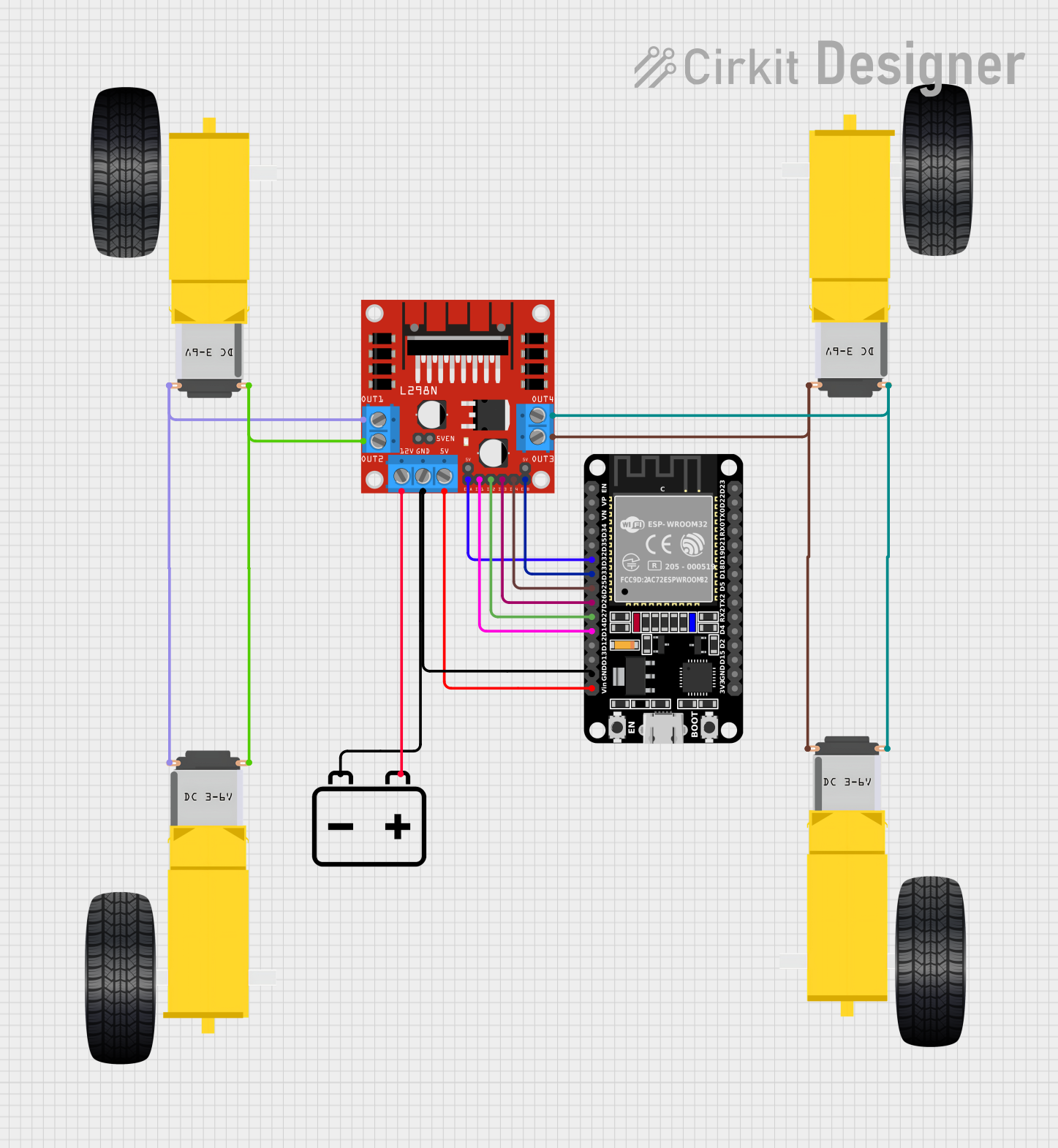
Q3: Can I use this motor driver with an ESP32 microcontroller?
Yes, the HS-F04A is compatible with the ESP32 microcontroller. Use the PWM pins on the ESP32 to control motor speed and direction.
Q4: How do I protect the motor driver from voltage spikes?
Use flyback diodes across the motor terminals to protect the driver from voltage spikes caused by inductive loads.