How to Use SMPS 12v 15A: Examples, Pinouts, and Specs
Introduction
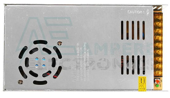
The Switched-Mode Power Supply (SMPS) 12V 15A is a highly efficient power supply unit designed to provide a stable 12-volt output with a maximum current of 15 amperes. This component is widely used in various electronic applications, including powering microcontrollers, LED strips, communication devices, and other electronic systems that require a reliable 12V power source.
Explore Projects Built with SMPS 12v 15A


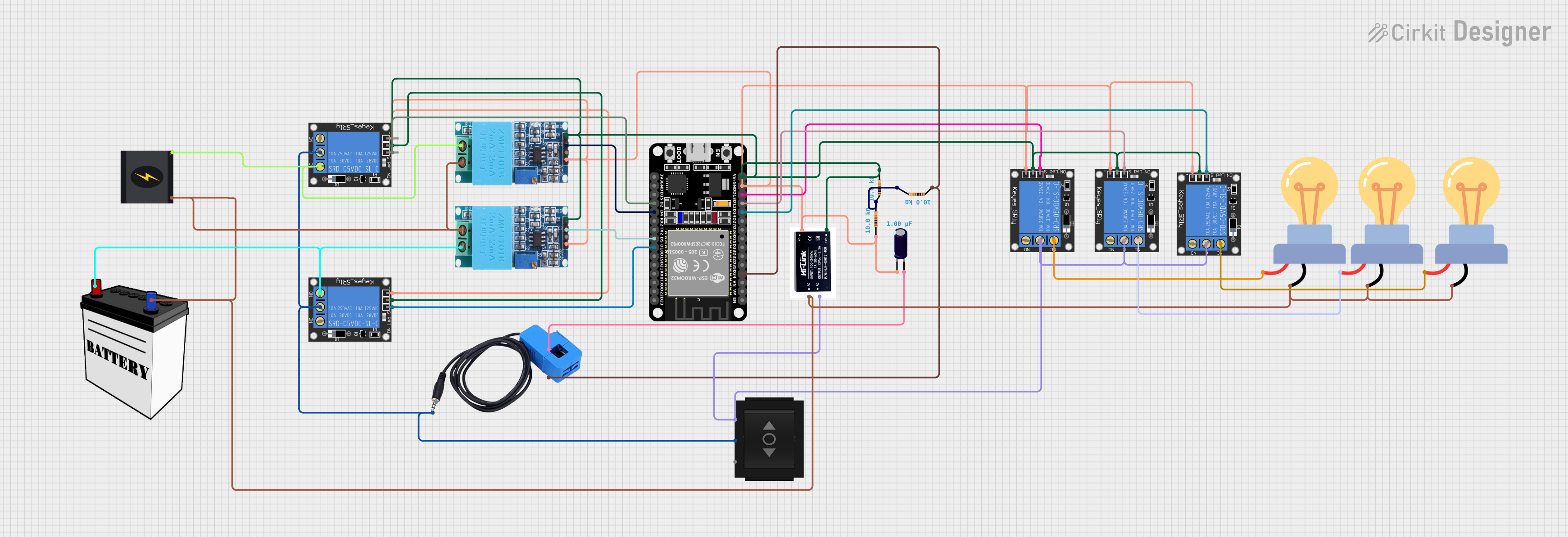
Explore Projects Built with SMPS 12v 15A
Technical Specifications
Key Technical Details
| Parameter | Value |
|---|---|
| Input Voltage | 100-240V AC |
| Output Voltage | 12V DC |
| Maximum Current | 15A |
| Power Rating | 180W |
| Efficiency | >85% |
| Ripple & Noise | <120mV |
| Operating Temp. | -10°C to +60°C |
| Storage Temp. | -20°C to +85°C |
| Dimensions | 200mm x 100mm x 50mm |
| Weight | 600g |
Pin Configuration and Descriptions
| Pin No. | Label | Description |
|---|---|---|
| 1 | L | Live AC input (100-240V) |
| 2 | N | Neutral AC input |
| 3 | GND | Ground (Earth) |
| 4 | +V | Positive DC output (12V) |
| 5 | -V | Negative DC output (Ground) |
| 6 | ADJ | Voltage adjustment (fine-tuning) |
Usage Instructions
How to Use the Component in a Circuit
- Safety First: Ensure the power supply is disconnected from the mains before making any connections.
- Connect AC Input: Connect the Live (L) and Neutral (N) pins to the AC mains supply. Ensure the ground (GND) is properly connected to avoid any electrical hazards.
- Connect DC Output: Connect the +V pin to the positive terminal of your load and the -V pin to the negative terminal (ground) of your load.
- Voltage Adjustment: If necessary, use the ADJ pin to fine-tune the output voltage. This is typically done using a small screwdriver to turn the potentiometer.
Important Considerations and Best Practices
- Heat Dissipation: Ensure adequate ventilation around the SMPS to prevent overheating. Consider using a heat sink or cooling fan if the unit is operating near its maximum capacity.
- Load Regulation: Avoid sudden changes in load to maintain a stable output voltage.
- Short Circuit Protection: The SMPS is equipped with short circuit protection, but it is still advisable to avoid short circuits to prolong the life of the unit.
- Grounding: Proper grounding is essential for safety and to minimize electrical noise.
Troubleshooting and FAQs
Common Issues and Solutions
No Output Voltage
- Check Connections: Ensure all connections are secure and correct.
- Input Voltage: Verify that the AC input voltage is within the specified range (100-240V).
- Fuse: Check if the internal fuse is blown and replace if necessary.
Output Voltage Fluctuations
- Load Stability: Ensure the load is stable and within the specified current range (up to 15A).
- Ventilation: Check for adequate ventilation and cooling to prevent overheating.
Overheating
- Cooling: Ensure proper ventilation and consider adding a cooling fan.
- Load: Verify that the load does not exceed the maximum power rating (180W).
FAQs
Q1: Can I use this SMPS to power my Arduino UNO?
- A1: Yes, you can use this SMPS to power your Arduino UNO. Connect the +V pin to the VIN pin on the Arduino and the -V pin to the GND pin on the Arduino.
Q2: How do I adjust the output voltage?
- A2: Use a small screwdriver to turn the potentiometer connected to the ADJ pin. Turn clockwise to increase the voltage and counterclockwise to decrease it.
Q3: What should I do if the SMPS is not working?
- A3: Check all connections, ensure the input voltage is correct, and verify that the internal fuse is not blown. If the problem persists, consult the manufacturer or a professional technician.
Example Code for Arduino UNO
Below is an example code to demonstrate how to power an Arduino UNO using the SMPS 12V 15A:
/*
 * Example code to demonstrate powering an Arduino UNO using SMPS 12V 15A.
 * Connect the +V pin of the SMPS to the VIN pin of the Arduino.
 * Connect the -V pin of the SMPS to the GND pin of the Arduino.
 */

void setup() {
  // Initialize serial communication at 9600 baud rate
  Serial.begin(9600);
  // Print a message to the serial monitor
  Serial.println("Arduino powered by SMPS 12V 15A");
}

void loop() {
  // Blink the built-in LED on pin 13
  digitalWrite(13, HIGH); // Turn the LED on
  delay(1000);            // Wait for 1 second
  digitalWrite(13, LOW);  // Turn the LED off
  delay(1000);            // Wait for 1 second
}
This documentation provides a comprehensive guide to using the SMPS 12V 15A, ensuring both beginners and experienced users can effectively utilize this component in their projects.