How to Use 7.0" TFT LCD Display 800x480 SSD1963 Panel Screen GT911 XPT2046 Touch Drive: Examples, Pinouts, and Specs
Introduction
The 7.0" TFT LCD Display with a resolution of 800x480 pixels is a high-quality display module designed for advanced graphical applications. It features the SSD1963 controller for driving the display and supports both capacitive (GT911) and resistive (XPT2046) touch interfaces. This versatile display is ideal for projects requiring a large, vibrant screen with touch functionality.
Explore Projects Built with 7.0" TFT LCD Display 800x480 SSD1963 Panel Screen GT911 XPT2046 Touch Drive


Explore Projects Built with 7.0" TFT LCD Display 800x480 SSD1963 Panel Screen GT911 XPT2046 Touch Drive
Common Applications and Use Cases
- Industrial control panels
- Home automation systems
- Embedded systems with graphical user interfaces
- DIY projects and prototyping
- Medical devices and instrumentation
Technical Specifications
Key Technical Details
- Display Size: 7.0 inches
- Resolution: 800x480 pixels (WVGA)
- Controller: SSD1963
- Touch Controllers: GT911 (capacitive) and XPT2046 (resistive)
- Interface: 16-bit/8-bit parallel interface
- Backlight: LED with adjustable brightness
- Operating Voltage: 3.3V for logic, 5V for backlight
- Touch Panel Type: Capacitive or resistive (depending on configuration)
- Viewing Angle: Wide-angle (up to 70° in all directions)
- Operating Temperature: -20°C to 70°C
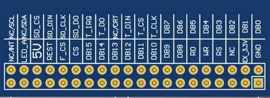
Pin Configuration and Descriptions
Display Interface Pins
| Pin Name | Description | Direction | Voltage Level |
|---|---|---|---|
| VCC | Power supply for the display | Input | 3.3V or 5V |
| GND | Ground | - | - |
| DB0-DB15 | Data bus pins (16-bit mode) | Input/Output | 3.3V |
| RS | Register select (command/data) | Input | 3.3V |
| WR | Write signal | Input | 3.3V |
| RD | Read signal | Input | 3.3V |
| CS | Chip select | Input | 3.3V |
| RESET | Reset signal | Input | 3.3V |
| BL_CTRL | Backlight control (PWM) | Input | 3.3V |
Touch Interface Pins (GT911/XPT2046)
| Pin Name | Description | Direction | Voltage Level |
|---|---|---|---|
| T_SCL | I2C clock for GT911 | Input | 3.3V |
| T_SDA | I2C data for GT911 | Input/Output | 3.3V |
| T_IRQ | Interrupt signal for GT911 | Output | 3.3V |
| T_CS | Chip select for XPT2046 | Input | 3.3V |
| T_CLK | SPI clock for XPT2046 | Input | 3.3V |
| T_DIN | SPI data input for XPT2046 | Input | 3.3V |
| T_DOUT | SPI data output for XPT2046 | Output | 3.3V |
| T_PENIRQ | Pen interrupt for XPT2046 | Output | 3.3V |
Usage Instructions
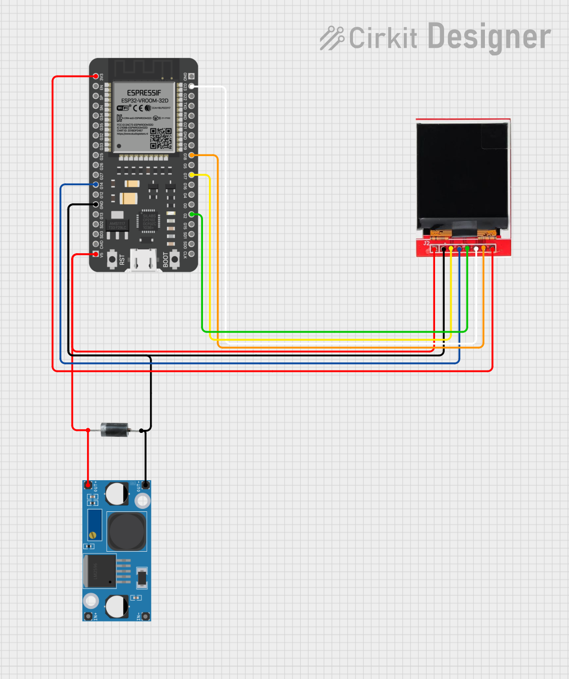
How to Use the Component in a Circuit
- Power Supply: Connect the VCC pin to a 3.3V or 5V power source and GND to ground.
- Data Interface: Use the DB0-DB15 pins for the 16-bit parallel interface. Connect these to the microcontroller or development board.
- Control Signals: Connect RS, WR, RD, CS, and RESET to the appropriate GPIO pins on your microcontroller.
- Backlight Control: Use the BL_CTRL pin to adjust the backlight brightness via PWM.
- Touch Interface:
- For capacitive touch (GT911), connect T_SCL, T_SDA, and T_IRQ to the I2C pins of your microcontroller.
- For resistive touch (XPT2046), connect T_CS, T_CLK, T_DIN, T_DOUT, and T_PENIRQ to the SPI pins.
Important Considerations and Best Practices
- Ensure the logic voltage levels of your microcontroller match the display's requirements (3.3V).
- Use decoupling capacitors near the power pins to reduce noise.
- For capacitive touch, ensure proper grounding to avoid interference.
- If using the resistive touch interface, calibrate the touch screen for accurate input detection.
Example Code for Arduino UNO
Below is an example of initializing the display and touch interface using the Arduino UNO:
#include <Adafruit_GFX.h>    // Graphics library
#include <MCUFRIEND_kbv.h>   // Library for SSD1963
#include <Wire.h>            // I2C library for GT911

MCUFRIEND_kbv tft;           // Create TFT object

void setup() {
  Serial.begin(9600);

  // Initialize the display
  uint16_t ID = tft.readID();
  if (ID == 0x1963) {
    tft.begin(ID);
    tft.setRotation(1);  // Set landscape orientation
    tft.fillScreen(0x0000);  // Clear screen (black)
    Serial.println("Display initialized successfully!");
  } else {
    Serial.println("Unknown display ID!");
  }

  // Initialize capacitive touch (GT911)
  Wire.begin();  // Start I2C communication
  Serial.println("Touch interface initialized!");
}

void loop() {
  // Example: Draw a rectangle on the screen
  tft.fillRect(50, 50, 200, 100, 0xF800);  // Red rectangle
  delay(1000);
}
Troubleshooting and FAQs
Common Issues and Solutions
Display Not Turning On:
- Check the power supply connections (VCC and GND).
- Verify the backlight control (BL_CTRL) is properly configured.
No Image or Incorrect Colors:
- Ensure the data bus (DB0-DB15) is correctly connected.
- Verify the control signals (RS, WR, RD, CS) are properly configured.
Touch Not Responding:
- For GT911, check the I2C connections (T_SCL, T_SDA) and ensure the interrupt pin (T_IRQ) is connected.
- For XPT2046, verify the SPI connections (T_CS, T_CLK, T_DIN, T_DOUT).
Flickering or Noise on the Display:
- Add decoupling capacitors near the power pins.
- Use shorter wires to reduce signal interference.
FAQs
Can I use this display with a 5V microcontroller? Yes, but you may need level shifters for the logic signals to avoid damaging the display.
How do I switch between capacitive and resistive touch? The touch interface is determined by the hardware configuration. Ensure the correct pins are connected for the desired touch controller.
What is the maximum refresh rate of the display? The refresh rate depends on the driving microcontroller and the interface speed. Typically, it can achieve up to 60Hz with proper configuration.
Can I use this display with Raspberry Pi? Yes, but you will need to configure the GPIO pins and use appropriate libraries for the SSD1963 controller.