
How to Use NRF24L01+ Breakout Board: Examples, Pinouts, and Specs

 Design with NRF24L01+ Breakout Board in Cirkit Designer
Introduction
The NRF24L01+ Breakout Board is a compact wireless transceiver module manufactured by Nordic Semiconductor (Part ID: nRF24L01+). It operates in the 2.4 GHz ISM band, enabling low-power, short-range communication between devices. This module is widely used in Internet of Things (IoT) applications, wireless sensor networks, and remote control systems due to its reliability, low cost, and ease of integration.
Explore Projects Built with NRF24L01+ Breakout Board
 Open Project in Cirkit Designer
 Open Project in Cirkit Designer
 Open Project in Cirkit Designer
 Open Project in Cirkit Designer
Explore Projects Built with NRF24L01+ Breakout Board
Open Project in Cirkit DesignerOpen Project in Cirkit DesignerOpen Project in Cirkit DesignerOpen Project in Cirkit DesignerCommon Applications
- Wireless data transmission in IoT devices
- Remote control systems (e.g., drones, RC cars)
- Wireless sensor networks
- Home automation systems
- Industrial monitoring and control
Technical Specifications
Key Technical Details
| Parameter | Value |
|---|---|
| Operating Frequency | 2.4 GHz ISM Band |
| Modulation Scheme | GFSK (Gaussian Frequency Shift Keying) |
| Data Rate | 250 kbps, 1 Mbps, 2 Mbps |
| Operating Voltage | 1.9V to 3.6V |
| Logic Level Compatibility | 3.3V |
| Maximum Output Power | 0 dBm (1 mW) |
| Sensitivity | -94 dBm at 250 kbps |
| Communication Range | Up to 100 meters (line of sight) |
| Current Consumption | 11.3 mA (TX at 0 dBm), 13.5 mA (RX mode) |
| Standby Current | 22 µA |
| Sleep Mode Current | 900 nA |
| Interface | SPI (Serial Peripheral Interface) |
| Number of Channels | 125 |
| Address Width | 3 to 5 bytes |
| Payload Size | 1 to 32 bytes |
Pin Configuration and Descriptions
The NRF24L01+ Breakout Board typically has an 8-pin header for interfacing with microcontrollers. Below is the pinout:
| Pin Number | Pin Name | Description |
|---|---|---|
| 1 | GND | Ground connection |
| 2 | VCC | Power supply (1.9V to 3.6V, typically 3.3V) |
| 3 | CE | Chip Enable: Activates RX or TX mode |
| 4 | CSN | Chip Select Not: SPI enable (active low) |
| 5 | SCK | Serial Clock: SPI clock input |
| 6 | MOSI | Master Out Slave In: SPI data input |
| 7 | MISO | Master In Slave Out: SPI data output |
| 8 | IRQ | Interrupt Request: Indicates data received or transmission complete (active low) |
Usage Instructions
How to Use the NRF24L01+ in a Circuit
- Power Supply: Connect the VCC pin to a 3.3V power source. Do not connect it directly to 5V as it may damage the module. Use a 3.3V regulator if your microcontroller operates at 5V.
- SPI Interface: Connect the SPI pins (CSN, SCK, MOSI, MISO) to the corresponding SPI pins on your microcontroller.
- CE Pin: Use a GPIO pin on your microcontroller to control the CE pin. Set it high to enable RX/TX mode and low for standby mode.
- IRQ Pin: Optionally connect the IRQ pin to a GPIO pin on your microcontroller to handle interrupts for events like data reception or transmission completion.
- Antenna: Ensure the onboard PCB antenna or external antenna (if applicable) is unobstructed for optimal signal strength.
Important Considerations
- Decoupling Capacitor: Place a 10 µF capacitor between VCC and GND near the module to stabilize the power supply.
- Voltage Level Shifting: If using a 5V microcontroller, use a level shifter or voltage divider for the SPI pins to avoid damaging the module.
- Signal Integrity: Keep SPI wires short to minimize noise and ensure reliable communication.
- Library Support: Use libraries like the RF24 library for Arduino to simplify communication with the module.
Example Code for Arduino UNO
Below is an example of how to use the NRF24L01+ with an Arduino UNO to send and receive data. This example uses the RF24 library.
#include <SPI.h>
#include <nRF24L01.h>
#include <RF24.h>

// Define CE and CSN pins
#define CE_PIN 9
#define CSN_PIN 10

// Create an RF24 object
RF24 radio(CE_PIN, CSN_PIN);

// Define the address for communication
const byte address[6] = "00001";

void setup() {
  Serial.begin(9600); // Initialize serial communication
  radio.begin();      // Initialize the NRF24L01+ module
  radio.openWritingPipe(address); // Set the address for transmission
  radio.setPALevel(RF24_PA_LOW);  // Set power level to low
  radio.stopListening();          // Set module to TX mode
}

void loop() {
  const char text[] = "Hello, World!"; // Data to send
  bool success = radio.write(&text, sizeof(text)); // Send data

  if (success) {
    Serial.println("Data sent successfully!");
  } else {
    Serial.println("Data transmission failed.");
  }

  delay(1000); // Wait 1 second before sending again
}
Notes:
- Install the RF24 library in the Arduino IDE via the Library Manager before running the code.
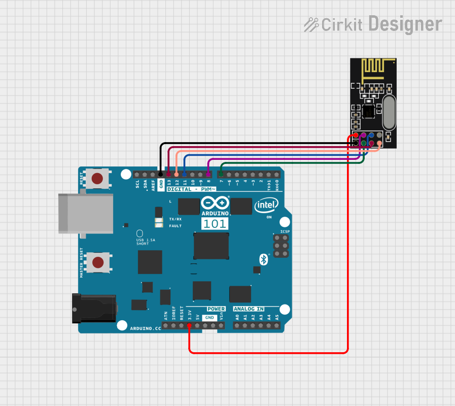
- Ensure proper wiring between the Arduino and the NRF24L01+ module.
Troubleshooting and FAQs
Common Issues and Solutions
Module Not Responding:
- Ensure the module is powered with 3.3V and not 5V.
- Check all connections, especially SPI pins.
- Add a decoupling capacitor (10 µF) near the module.
Poor Communication Range:
- Ensure the antenna is unobstructed and positioned correctly.
- Reduce the data rate to 250 kbps for better range.
- Check for interference from other 2.4 GHz devices.
Data Transmission Fails:
- Verify that both transmitter and receiver use the same address and channel.
- Ensure the CE pin is set high during transmission or reception.
High Power Consumption:
- Use the module's power-down mode when not actively transmitting or receiving.
- Ensure the module is not in constant TX mode unnecessarily.
FAQs
Q: Can the NRF24L01+ module communicate with Bluetooth devices?
A: No, the NRF24L01+ uses the 2.4 GHz ISM band but does not support Bluetooth protocols.
Q: What is the maximum range of the NRF24L01+?
A: The range is up to 100 meters in line-of-sight conditions. Obstacles and interference can reduce this range.
Q: Can I use multiple NRF24L01+ modules in the same network?
A: Yes, the module supports multi-node communication using unique addresses for each device.
Q: Is the NRF24L01+ compatible with 5V microcontrollers?
A: The module operates at 3.3V. Use a level shifter or voltage divider for SPI pins when interfacing with 5V microcontrollers.