How to Use arduino nano: Examples, Pinouts, and Specs
Introduction
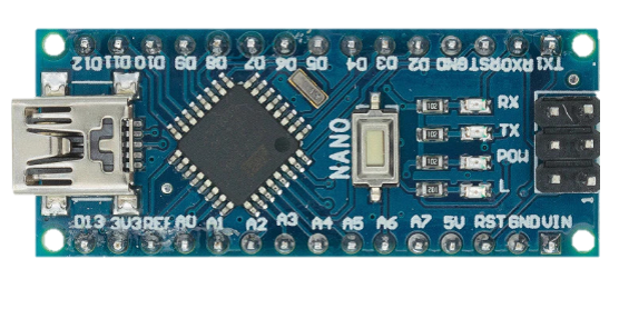
The Arduino Nano is a compact microcontroller board developed by Arduino, based on the ATmega328P microcontroller. It is designed for easy integration into electronic projects, offering a small form factor while maintaining powerful functionality. The Nano is equipped with digital and analog input/output pins, USB connectivity for programming and communication, and a wide range of features that make it ideal for prototyping and embedded systems.
Explore Projects Built with arduino nano

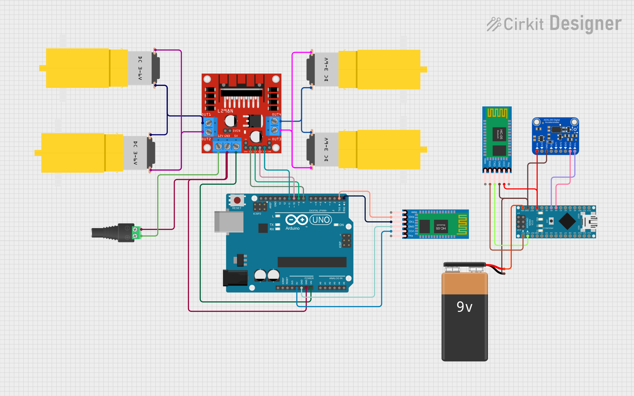
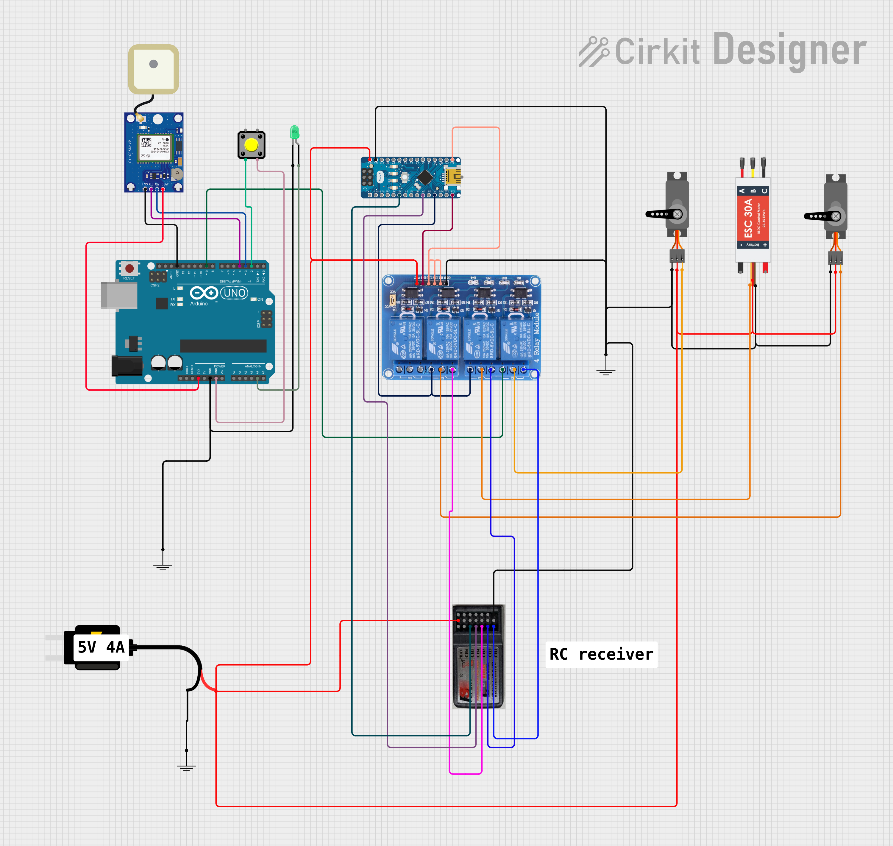

Explore Projects Built with arduino nano
Common Applications and Use Cases
- DIY electronics and prototyping
- Robotics and automation systems
- IoT (Internet of Things) devices
- Sensor data acquisition and processing
- Wearable technology
- Educational projects and learning platforms
Technical Specifications
The Arduino Nano is a versatile board with the following key technical details:
| Specification | Details |
|---|---|
| Microcontroller | ATmega328P |
| Operating Voltage | 5V |
| Input Voltage (VIN) | 7-12V |
| Digital I/O Pins | 14 (6 PWM outputs) |
| Analog Input Pins | 8 |
| DC Current per I/O Pin | 40 mA |
| Flash Memory | 32 KB (2 KB used by bootloader) |
| SRAM | 2 KB |
| EEPROM | 1 KB |
| Clock Speed | 16 MHz |
| USB Connectivity | Mini-B USB |
| Dimensions | 18 x 45 mm |
Pin Configuration and Descriptions
The Arduino Nano has a total of 30 pins, including power, digital, and analog pins. Below is a detailed pinout description:
Power Pins
| Pin | Name | Description |
|---|---|---|
| 1 | VIN | Input voltage to the board when using an external power source (7-12V). |
| 2 | 5V | Regulated 5V output from the onboard voltage regulator. |
| 3 | 3.3V | Regulated 3.3V output (maximum current: 50 mA). |
| 4 | GND | Ground pins (multiple GND pins available). |
| 5 | RESET | Resets the microcontroller when pulled LOW. |
Digital Pins
| Pin | Name | Description |
|---|---|---|
| D0-D13 | Digital I/O | General-purpose digital input/output pins. Pins D3, D5, D6, D9, D10, and D11 support PWM. |
Analog Pins
| Pin | Name | Description |
|---|---|---|
| A0-A7 | Analog Input | Used for reading analog signals (0-5V). Can also be used as digital I/O pins. |
Communication Pins
| Pin | Name | Description |
|---|---|---|
| D0, D1 | RX, TX | UART communication pins for serial communication. |
| D10-D13 | SPI | SPI communication pins (SS, MOSI, MISO, SCK). |
| A4, A5 | I2C | I2C communication pins (SDA, SCL). |
Usage Instructions
How to Use the Arduino Nano in a Circuit
Powering the Board:
- Connect the Nano to your computer via a Mini-B USB cable for programming and power.
- Alternatively, supply power through the VIN pin (7-12V) or the 5V pin (regulated 5V).
Programming the Board:
- Install the Arduino IDE from the official Arduino website.
- Select "Arduino Nano" as the board type and choose the correct processor (ATmega328P).
- Connect the Nano to your computer and upload your code via the USB cable.
Connecting Components:
- Use the digital pins (D0-D13) for digital input/output operations.
- Use the analog pins (A0-A7) for reading analog signals or as additional digital I/O pins.
- For communication, use the UART (D0, D1), SPI (D10-D13), or I2C (A4, A5) interfaces.
Important Considerations and Best Practices
- Avoid exceeding the maximum current rating of 40 mA per I/O pin to prevent damage.
- Use pull-up or pull-down resistors for stable digital input signals.
- Ensure proper grounding when connecting external components to avoid noise or instability.
- When using the Nano with motors or high-power devices, use external power supplies and isolation circuits.
Example Code for Arduino Nano with an LED
The following example demonstrates how to blink an LED connected to pin D13:
// Blink an LED connected to pin D13
// This example toggles the LED ON and OFF every second.

void setup() {
  pinMode(13, OUTPUT); // Set pin D13 as an output
}

void loop() {
  digitalWrite(13, HIGH); // Turn the LED ON
  delay(1000);            // Wait for 1 second
  digitalWrite(13, LOW);  // Turn the LED OFF
  delay(1000);            // Wait for 1 second
}
Troubleshooting and FAQs
Common Issues and Solutions
The Arduino Nano is not detected by the computer:
- Ensure the USB cable is functional and supports data transfer.
- Install the correct USB driver for the Nano (CH340 driver for some clones).
Code upload fails with an error:
- Verify that the correct board and processor are selected in the Arduino IDE.
- Check the COM port in the IDE and ensure it matches the Nano's port.
The board resets unexpectedly:
- Ensure the power supply is stable and within the recommended voltage range.
- Avoid drawing excessive current from the I/O pins.
Analog readings are unstable:
- Use proper grounding and shielding for analog sensors.
- Add decoupling capacitors near the sensor connections.
FAQs
Q: Can the Arduino Nano run on 3.3V?
A: While the Nano has a 3.3V output pin, the board itself is designed to operate at 5V. Running it at 3.3V is not recommended as it may cause instability.
Q: How do I reset the Arduino Nano?
A: You can reset the Nano by pressing the onboard reset button or pulling the RESET pin LOW momentarily.
Q: Can I use the Arduino Nano for battery-powered projects?
A: Yes, the Nano can be powered using batteries via the VIN pin (7-12V) or the 5V pin (regulated). Ensure the battery voltage matches the input requirements.
Q: What is the difference between the Arduino Nano and Arduino Uno?
A: The Nano is smaller and more compact than the Uno, making it ideal for space-constrained projects. Both use the same ATmega328P microcontroller and have similar functionality.