How to Use KY-021: Examples, Pinouts, and Specs
Introduction
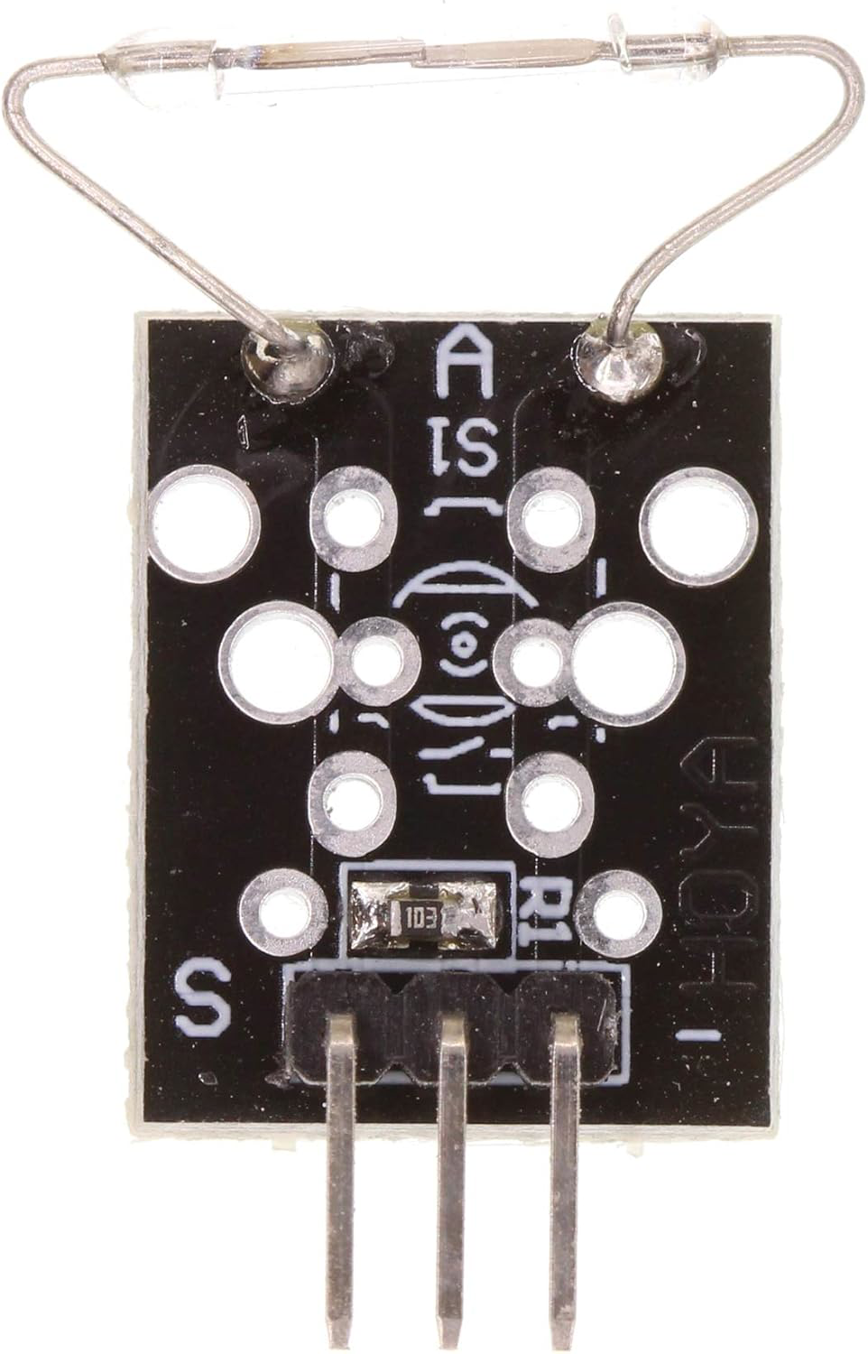
The KY-021 is a temperature sensor module that utilizes the LM35 temperature sensor. It provides an analog output that is directly proportional to the temperature in degrees Celsius. This module is widely used in temperature monitoring and control applications due to its simplicity, accuracy, and ease of integration with microcontrollers and other electronic systems.
Explore Projects Built with KY-021


Explore Projects Built with KY-021
Common Applications and Use Cases
- Environmental temperature monitoring
- HVAC systems
- Industrial temperature control
- Weather stations
- Home automation systems
- Educational projects and prototyping
Technical Specifications
The KY-021 module is based on the LM35 temperature sensor, which is known for its linear output and high accuracy. Below are the key technical details:
| Parameter | Value |
|---|---|
| Operating Voltage | 4V to 30V |
| Output Voltage Range | 0V to 1.5V (for 0°C to 150°C) |
| Temperature Range | -55°C to +150°C |
| Accuracy | ±0.5°C (at 25°C) |
| Output Sensitivity | 10mV/°C |
| Power Consumption | Low |
| Dimensions | 18mm x 10mm x 8mm |
Pin Configuration and Descriptions
The KY-021 module has three pins for easy interfacing:
| Pin | Name | Description |
|---|---|---|
| 1 | VCC | Power supply pin (4V to 30V) |
| 2 | GND | Ground pin |
| 3 | OUT | Analog output pin that provides a voltage proportional to the temperature |
Usage Instructions
How to Use the KY-021 in a Circuit
- Power the Module: Connect the
VCCpin to a 5V power supply (or any voltage within the operating range) and theGNDpin to the ground of your circuit. - Read the Output: Connect the
OUTpin to an analog input pin of a microcontroller (e.g., Arduino UNO) or an analog-to-digital converter (ADC) to measure the output voltage. - Calculate the Temperature: The output voltage is proportional to the temperature in degrees Celsius. Use the formula: [ \text{Temperature (°C)} = \frac{\text{Output Voltage (mV)}}{10} ]
Important Considerations and Best Practices
- Ensure the power supply voltage is within the specified range to avoid damaging the module.
- Place the sensor in a location where it can accurately measure the ambient temperature without interference from heat sources or airflow.
- Use decoupling capacitors (e.g., 0.1µF) near the power supply pins to reduce noise in the output signal.
- If using the module in a noisy environment, consider shielding the sensor or using a low-pass filter to improve accuracy.
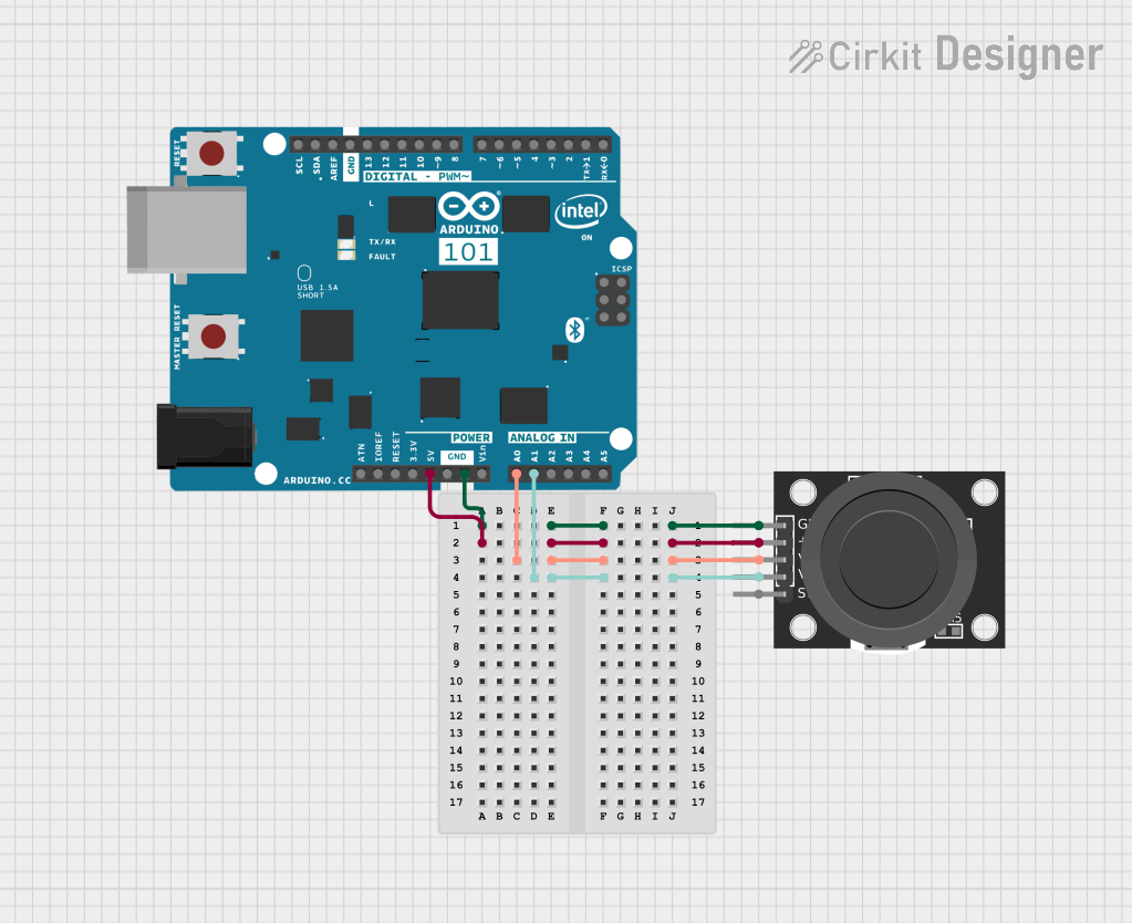
Example: Connecting KY-021 to Arduino UNO
Below is an example of how to connect and read data from the KY-021 module using an Arduino UNO:
Circuit Connections
- Connect the
VCCpin of the KY-021 to the 5V pin of the Arduino. - Connect the
GNDpin of the KY-021 to the GND pin of the Arduino. - Connect the
OUTpin of the KY-021 to the A0 analog input pin of the Arduino.
Arduino Code
// KY-021 Temperature Sensor Example with Arduino UNO
// Reads the analog output from the KY-021 and calculates the temperature in °C

const int sensorPin = A0; // KY-021 OUT pin connected to Arduino A0
float voltage;            // Variable to store the sensor output voltage
float temperature;        // Variable to store the calculated temperature

void setup() {
  Serial.begin(9600); // Initialize serial communication at 9600 baud
}

void loop() {
  int sensorValue = analogRead(sensorPin); // Read the analog value from the sensor
  voltage = sensorValue * (5.0 / 1023.0);  // Convert the analog value to voltage
  temperature = voltage * 100.0;          // Convert voltage to temperature (°C)

  // Print the temperature to the Serial Monitor
  Serial.print("Temperature: ");
  Serial.print(temperature);
  Serial.println(" °C");

  delay(1000); // Wait for 1 second before the next reading
}
Troubleshooting and FAQs
Common Issues and Solutions
No Output or Incorrect Readings
- Cause: Incorrect wiring or loose connections.
- Solution: Double-check the connections and ensure the pins are properly connected.
Fluctuating or Noisy Output
- Cause: Electrical noise or interference in the circuit.
- Solution: Add a decoupling capacitor (e.g., 0.1µF) near the power supply pins or use a low-pass filter.
Output Voltage Does Not Change with Temperature
- Cause: Faulty sensor or incorrect power supply voltage.
- Solution: Verify the power supply voltage and replace the sensor if necessary.
Temperature Readings Are Inaccurate
- Cause: Sensor placement near heat sources or airflow.
- Solution: Relocate the sensor to a more suitable location for accurate measurements.
FAQs
Q1: Can the KY-021 measure negative temperatures?
Yes, the LM35 sensor used in the KY-021 can measure temperatures as low as -55°C. However, for negative temperatures, the output voltage will be below 0V, which may require additional circuitry to read.
Q2: Can I use the KY-021 with a 3.3V microcontroller?
Yes, the KY-021 can operate with a power supply as low as 4V. However, ensure the output voltage range is compatible with the ADC of your microcontroller.
Q3: How do I improve the accuracy of the KY-021?
To improve accuracy, ensure the sensor is placed in a stable environment, use proper decoupling capacitors, and calibrate the sensor if necessary.
Q4: Is the KY-021 waterproof?
No, the KY-021 is not waterproof. If you need to measure temperature in wet environments, consider using a waterproof temperature sensor like the DS18B20.