How to Use RTC DS1302: Examples, Pinouts, and Specs
Introduction
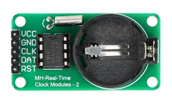
The DS1302 is a real-time clock (RTC) module designed to keep track of the current time and date, including seconds, minutes, hours, day, date, month, and year. It features a serial interface for communication with microcontrollers and includes a battery backup, allowing it to maintain accurate timekeeping even during power outages. The DS1302 is widely used in applications requiring precise timekeeping, such as data loggers, alarm systems, and embedded systems.
Explore Projects Built with RTC DS1302

Explore Projects Built with RTC DS1302
Common Applications
- Digital clocks and timers
- Data logging systems
- Alarm systems
- Home automation
- Time-stamping in embedded systems
Technical Specifications
The DS1302 is a low-power RTC with the following key specifications:
| Parameter | Value |
|---|---|
| Operating Voltage | 2.0V to 5.5V |
| Backup Battery Voltage | 2.0V to 3.5V |
| Operating Temperature | -40°C to +85°C |
| Timekeeping Accuracy | ±2 minutes per month (at 25°C) |
| Communication Interface | Serial (3-wire) |
| Current Consumption | < 300nA (with battery backup) |
| Clock Format | 12-hour or 24-hour mode |
| Memory | 31 bytes of user-accessible RAM |
Pin Configuration
The DS1302 has 8 pins, with the following configuration:
| Pin Number | Pin Name | Description |
|---|---|---|
| 1 | VCC1 | Primary power supply (2.0V to 5.5V) |
| 2 | X1 | Oscillator input (32.768 kHz crystal) |
| 3 | X2 | Oscillator output (32.768 kHz crystal) |
| 4 | GND | Ground |
| 5 | RST | Reset (active high, used to initiate communication) |
| 6 | I/O | Data input/output (bidirectional) |
| 7 | SCLK | Serial clock input |
| 8 | VCC2 | Backup battery input (2.0V to 3.5V) |
Usage Instructions
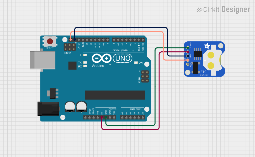
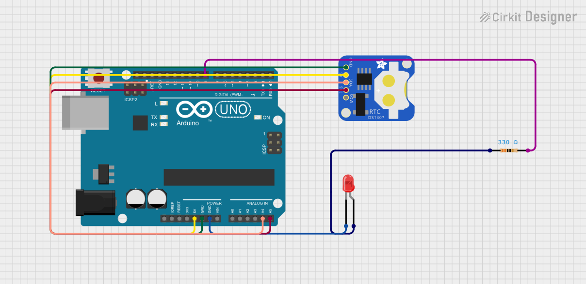
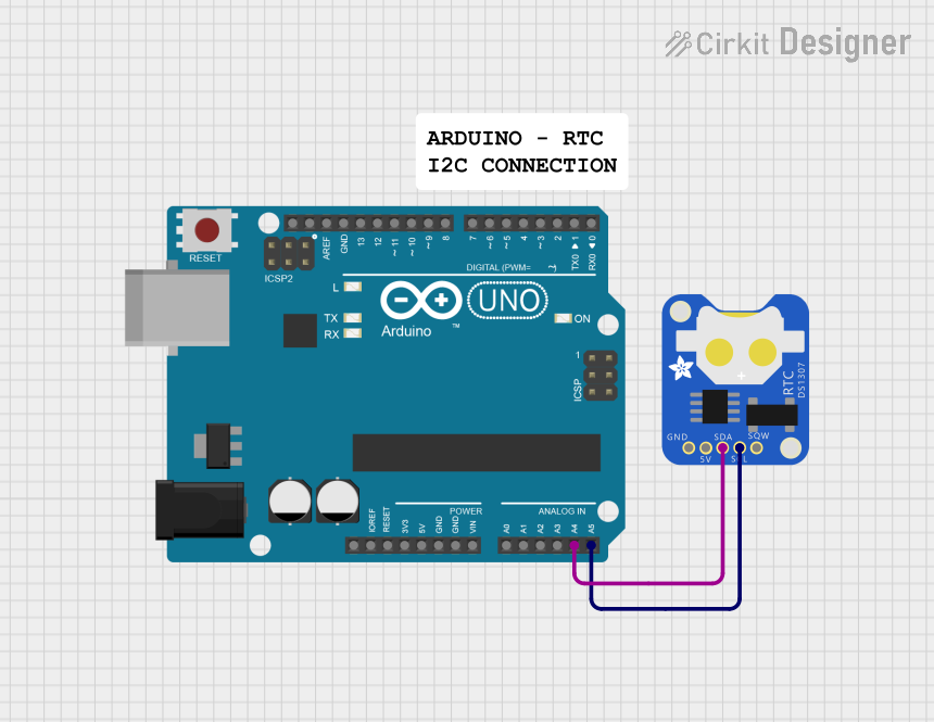
Connecting the DS1302 to a Microcontroller
To use the DS1302 in a circuit, connect it to a microcontroller (e.g., Arduino UNO) as follows:
- Connect the VCC1 pin to the 5V power supply of the microcontroller.
- Connect the GND pin to the ground of the microcontroller.
- Attach a 32.768 kHz crystal oscillator to the X1 and X2 pins.
- Connect the RST, I/O, and SCLK pins to digital pins on the microcontroller.
- Optionally, connect a backup battery (e.g., a CR2032 coin cell) to the VCC2 pin.
Example Arduino Code
Below is an example Arduino sketch to interface with the DS1302 and display the time on the serial monitor:
#include <DS1302.h> // Include the DS1302 library

// Define the pins connected to the DS1302
#define RST_PIN 4   // Reset pin
#define IO_PIN  5   // Data I/O pin
#define SCLK_PIN 6  // Serial clock pin

// Create an instance of the DS1302 class
DS1302 rtc(RST_PIN, IO_PIN, SCLK_PIN);

void setup() {
  Serial.begin(9600); // Initialize serial communication
  rtc.halt(false);    // Start the RTC
  rtc.writeProtect(false); // Disable write protection

  // Set the date and time (Year, Month, Day, Hour, Minute, Second)
  rtc.setDateTime(2023, 10, 15, 14, 30, 0);
  // Adjust the above values as needed
}

void loop() {
  // Read the current date and time from the RTC
  DS1302::DateTime now = rtc.getDateTime();

  // Print the date and time to the serial monitor
  Serial.print("Date: ");
  Serial.print(now.year); Serial.print("-");
  Serial.print(now.month); Serial.print("-");
  Serial.println(now.day);

  Serial.print("Time: ");
  Serial.print(now.hour); Serial.print(":");
  Serial.print(now.minute); Serial.print(":");
  Serial.println(now.second);

  delay(1000); // Wait for 1 second before updating
}
Best Practices
- Use a decoupling capacitor (e.g., 0.1 µF) between the VCC1 and GND pins to reduce noise.
- Ensure the backup battery voltage is within the specified range (2.0V to 3.5V).
- Avoid frequent writes to the RTC to extend its lifespan.
- Use a pull-up resistor (e.g., 10kΩ) on the I/O pin if communication issues occur.
Troubleshooting and FAQs
Common Issues
RTC not keeping time accurately:
- Ensure the 32.768 kHz crystal oscillator is properly connected to the X1 and X2 pins.
- Verify that the backup battery is functional and within the specified voltage range.
No communication with the microcontroller:
- Check the connections to the RST, I/O, and SCLK pins.
- Ensure the microcontroller pins are correctly defined in the code.
Time resets after power loss:
- Confirm that a backup battery is connected to the VCC2 pin.
- Verify that the battery voltage is sufficient (2.0V to 3.5V).
FAQs
Q: Can the DS1302 operate without a backup battery?
A: Yes, but it will lose the time and date settings during power outages.
Q: How do I switch between 12-hour and 24-hour modes?
A: The DS1302 supports both modes. You can configure the hour format in the software by setting the appropriate bit in the hour register.
Q: What is the purpose of the 31 bytes of RAM?
A: The RAM can be used to store user data that needs to be retained during power outages, such as configuration settings or small logs.
Q: Can I use the DS1302 with a 3.3V microcontroller?
A: Yes, the DS1302 operates at voltages as low as 2.0V, making it compatible with 3.3V systems.