How to Use vibration motor module: Examples, Pinouts, and Specs
Introduction
A vibration motor module is a small device that converts electrical energy into mechanical vibration. It typically consists of a DC motor with an unbalanced weight attached to its shaft, which creates vibrations when the motor spins. These modules are commonly used in mobile devices, gaming controllers, and wearable technology to provide haptic feedback.
In addition to haptic feedback, vibration motor modules are also used in alert systems, robotics, and interactive projects to provide tactile notifications or enhance user experience.
Explore Projects Built with vibration motor module

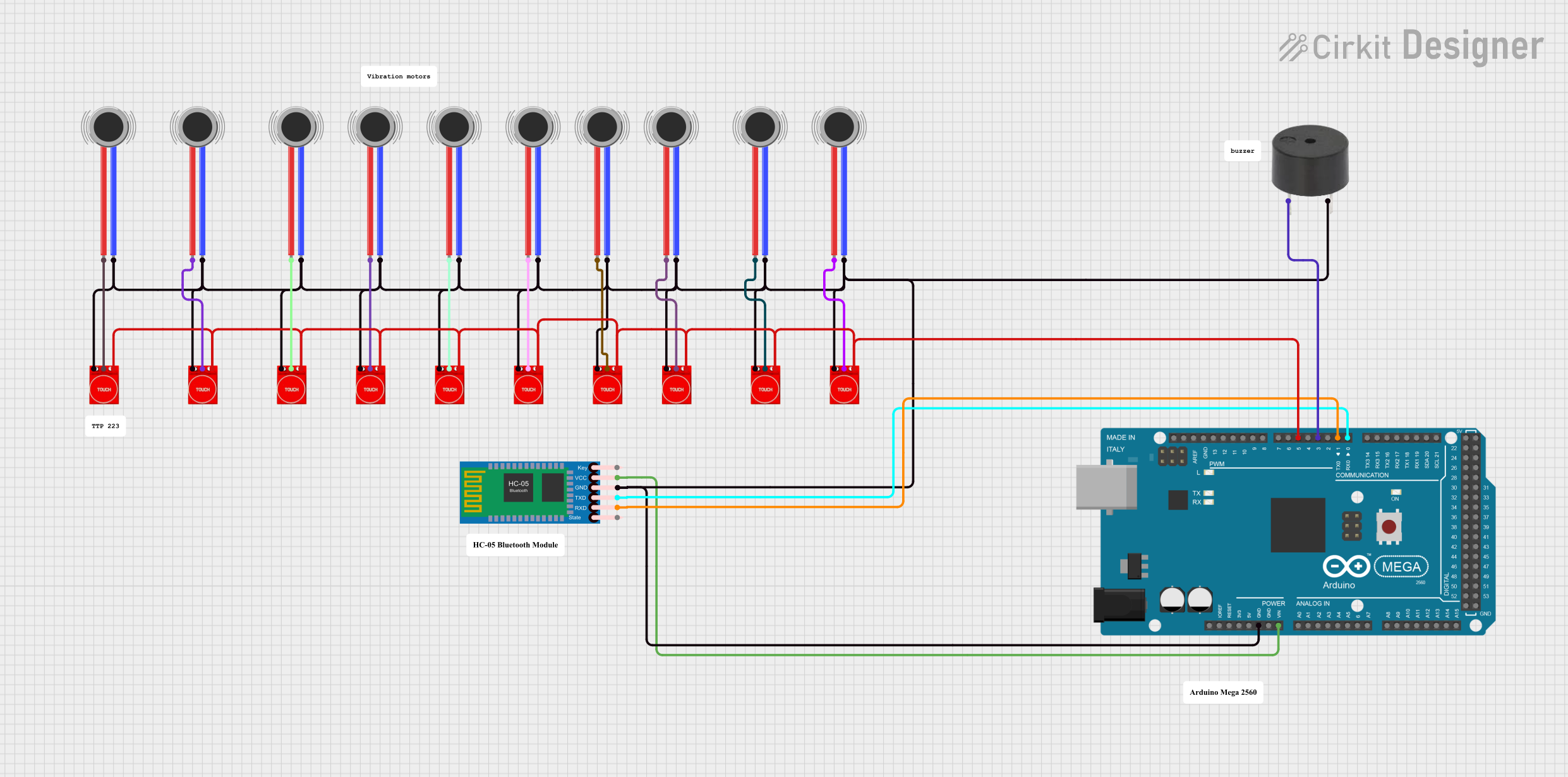
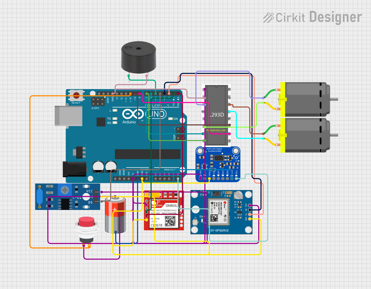
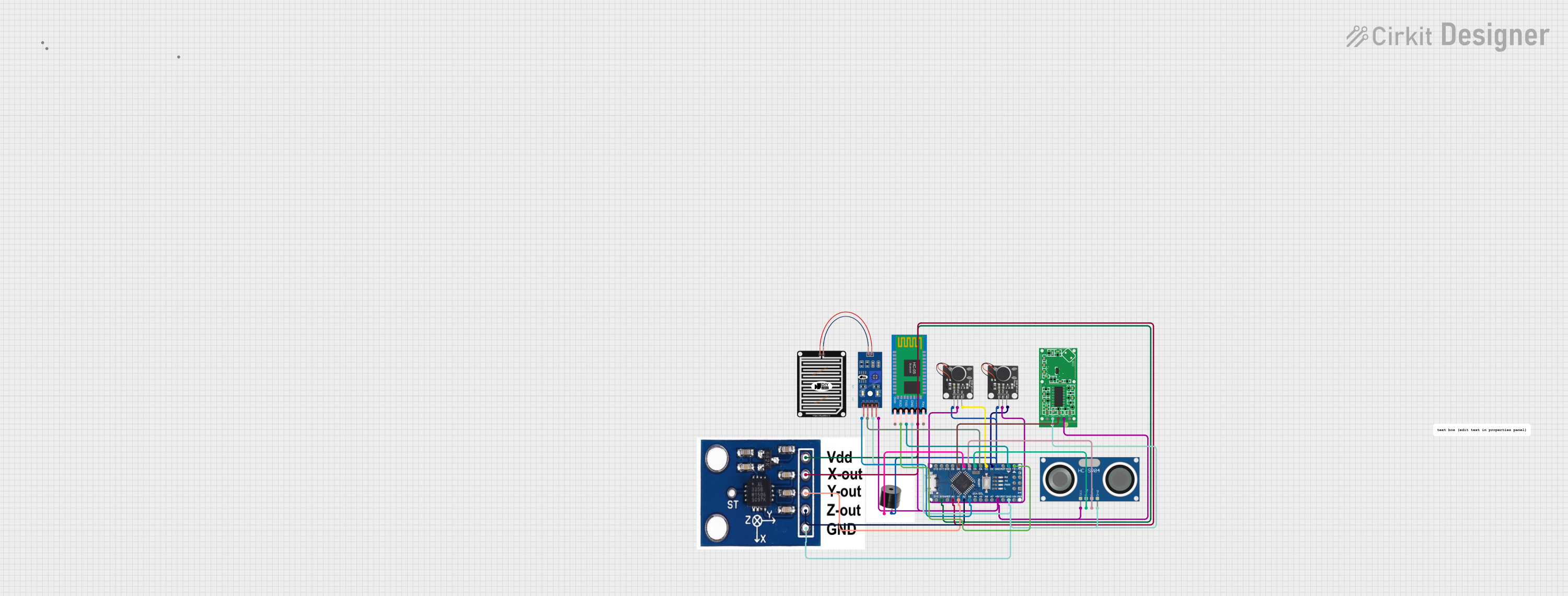
Explore Projects Built with vibration motor module
Technical Specifications
Below are the key technical details of a typical vibration motor module:
| Parameter | Value |
|---|---|
| Operating Voltage | 3.3V to 5V |
| Operating Current | 80mA to 120mA |
| Motor Type | DC motor with unbalanced weight |
| Vibration Frequency | ~100 Hz (varies with voltage) |
| Dimensions | ~27mm x 12mm x 10mm |
| Weight | ~5g |
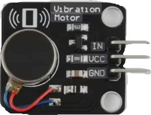
Pin Configuration and Descriptions
The vibration motor module typically has three pins:
| Pin | Name | Description |
|---|---|---|
| 1 | VCC | Power supply pin. Connect to 3.3V or 5V depending on the module specifications. |
| 2 | GND | Ground pin. Connect to the ground of the power supply. |
| 3 | Signal/IN | Control pin. Used to turn the motor on or off via a microcontroller or switch. |
Usage Instructions
How to Use the Vibration Motor Module in a Circuit
- Power Connection: Connect the
VCCpin to a 3.3V or 5V power source and theGNDpin to the ground. - Control Signal: Use the
Signal/INpin to control the motor. This pin can be connected to a microcontroller (e.g., Arduino) or a simple switch. - Driving the Motor: The motor can be directly driven by the control pin if the current requirements are met. For higher currents, use a transistor or MOSFET as a driver.
Important Considerations and Best Practices
- Power Supply: Ensure the power supply can provide sufficient current (80mA to 120mA) to drive the motor.
- PWM Control: Use Pulse Width Modulation (PWM) on the
Signal/INpin to adjust the vibration intensity. - Decoupling Capacitor: Add a decoupling capacitor (e.g., 100µF) across the power supply pins to reduce noise and voltage fluctuations.
- Mounting: Secure the module firmly to prevent unwanted movement during operation.
- Heat Dissipation: Avoid prolonged operation at maximum voltage to prevent overheating.
Example: Using the Vibration Motor Module with Arduino UNO
Below is an example of how to control the vibration motor module using an Arduino UNO:
// Define the pin connected to the Signal/IN pin of the vibration motor module
const int motorPin = 9;

void setup() {
  // Set the motor pin as an output
  pinMode(motorPin, OUTPUT);
}

void loop() {
  // Turn the motor on
  digitalWrite(motorPin, HIGH);
  delay(1000); // Keep the motor on for 1 second

  // Turn the motor off
  digitalWrite(motorPin, LOW);
  delay(1000); // Keep the motor off for 1 second
}
In this example:
- The motor is connected to pin 9 of the Arduino.
- The motor alternates between being on for 1 second and off for 1 second.
Troubleshooting and FAQs
Common Issues and Solutions
Motor Not Vibrating
- Cause: Insufficient power supply.
- Solution: Verify that the power supply provides the required voltage and current.
Weak or No Vibration
- Cause: Low input voltage or damaged motor.
- Solution: Check the input voltage and ensure it matches the module's specifications. Replace the motor if necessary.
Excessive Noise
- Cause: Loose mounting or unbalanced weight.
- Solution: Secure the module firmly and inspect the motor for physical damage.
Overheating
- Cause: Prolonged operation at maximum voltage.
- Solution: Reduce the operating voltage or limit the runtime.
FAQs
Q1: Can I control the vibration intensity?
A1: Yes, you can control the vibration intensity by using PWM on the Signal/IN pin. Adjust the duty cycle to vary the motor speed and vibration strength.
Q2: Can I use the module with a 12V power supply?
A2: No, most vibration motor modules are designed for 3.3V to 5V operation. Using a higher voltage may damage the motor.
Q3: Is it safe to connect the module directly to an Arduino pin?
A3: Yes, if the motor's current requirements are within the Arduino's pin current limits (40mA max per pin). Otherwise, use a transistor or MOSFET as a driver.
Q4: Can I use this module in battery-powered projects?
A4: Yes, but ensure the battery can supply sufficient current for the motor. A rechargeable Li-ion or NiMH battery is recommended.