
How to Use Adafruit Infrared IR Remote Receiver: Examples, Pinouts, and Specs
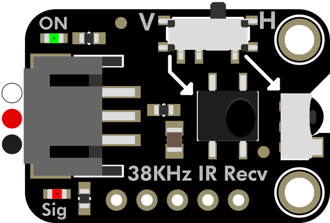
 Design with Adafruit Infrared IR Remote Receiver in Cirkit Designer
Introduction
The Adafruit Infrared IR Remote Receiver (Manufacturer Part ID: 5939) is a compact and reliable sensor designed to detect infrared (IR) signals from remote controls. This component enables wireless communication and control of electronic devices by decoding IR signals transmitted by standard remote controls. It is widely used in home automation, robotics, and consumer electronics projects.
Explore Projects Built with Adafruit Infrared IR Remote Receiver
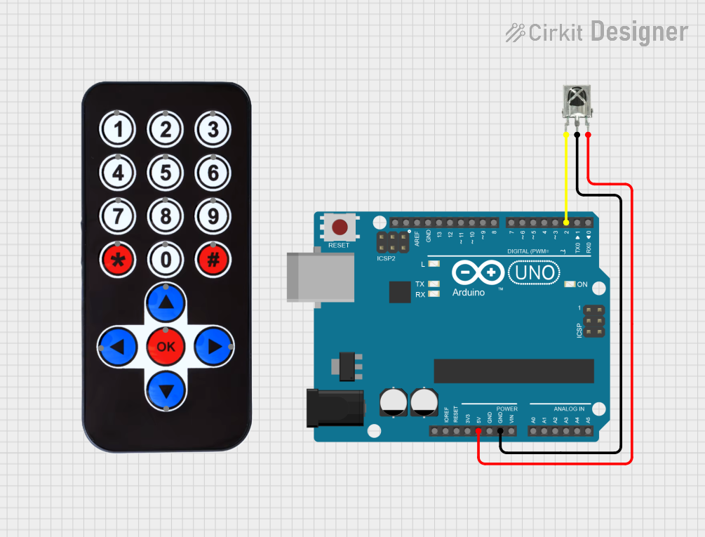 Open Project in Cirkit Designer
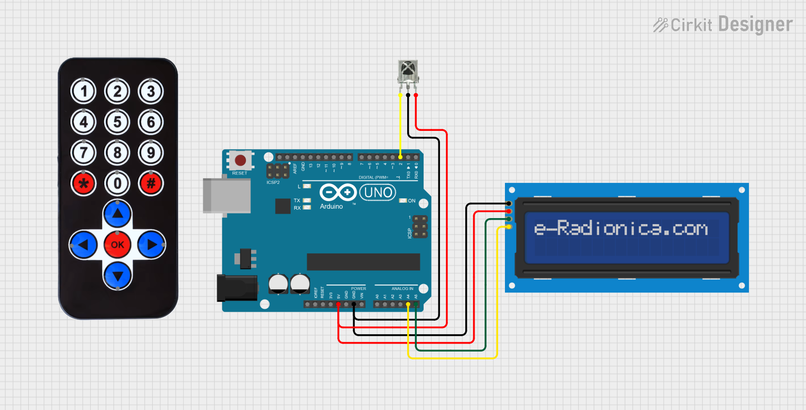 Open Project in Cirkit Designer
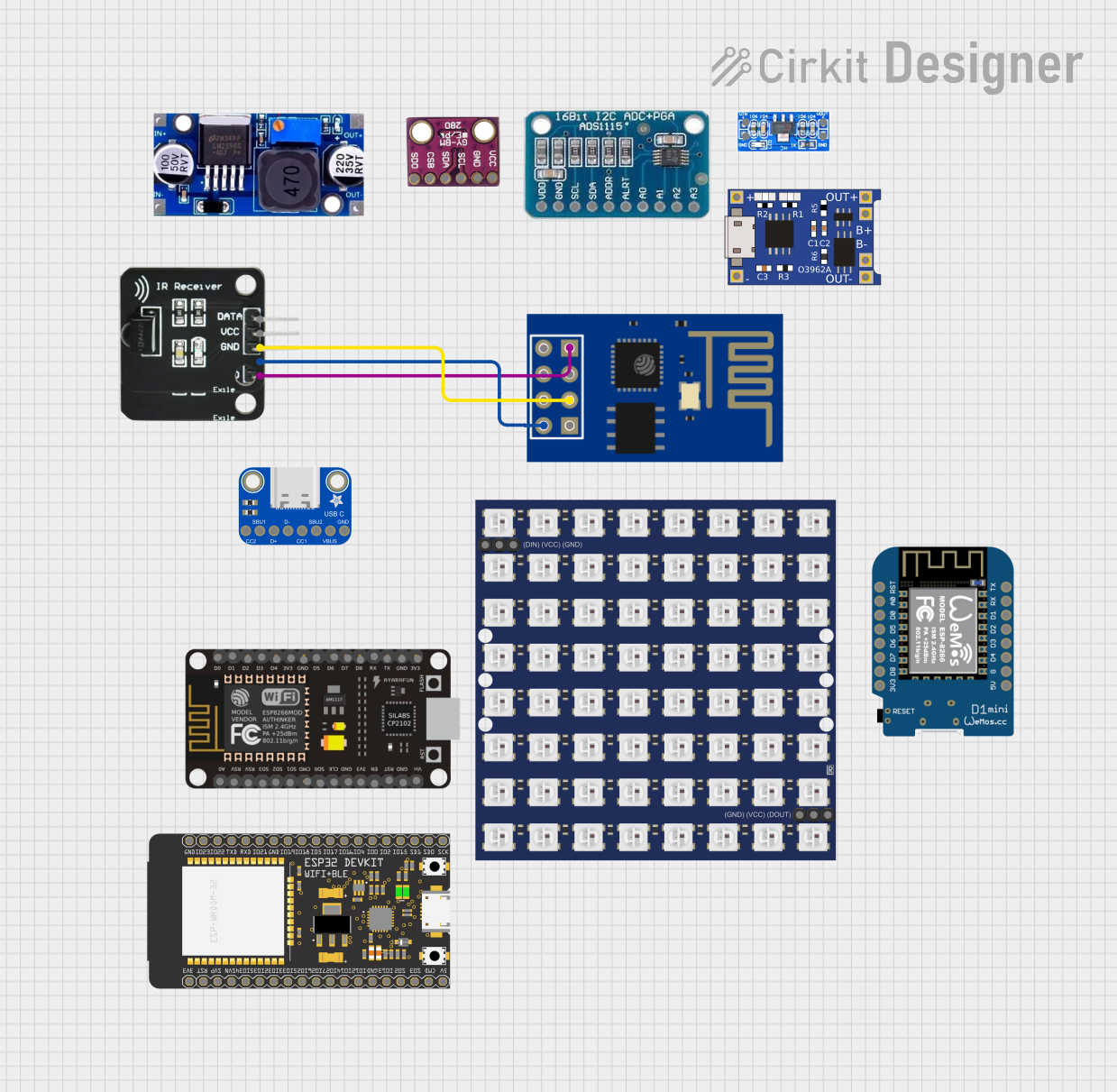 Open Project in Cirkit Designer
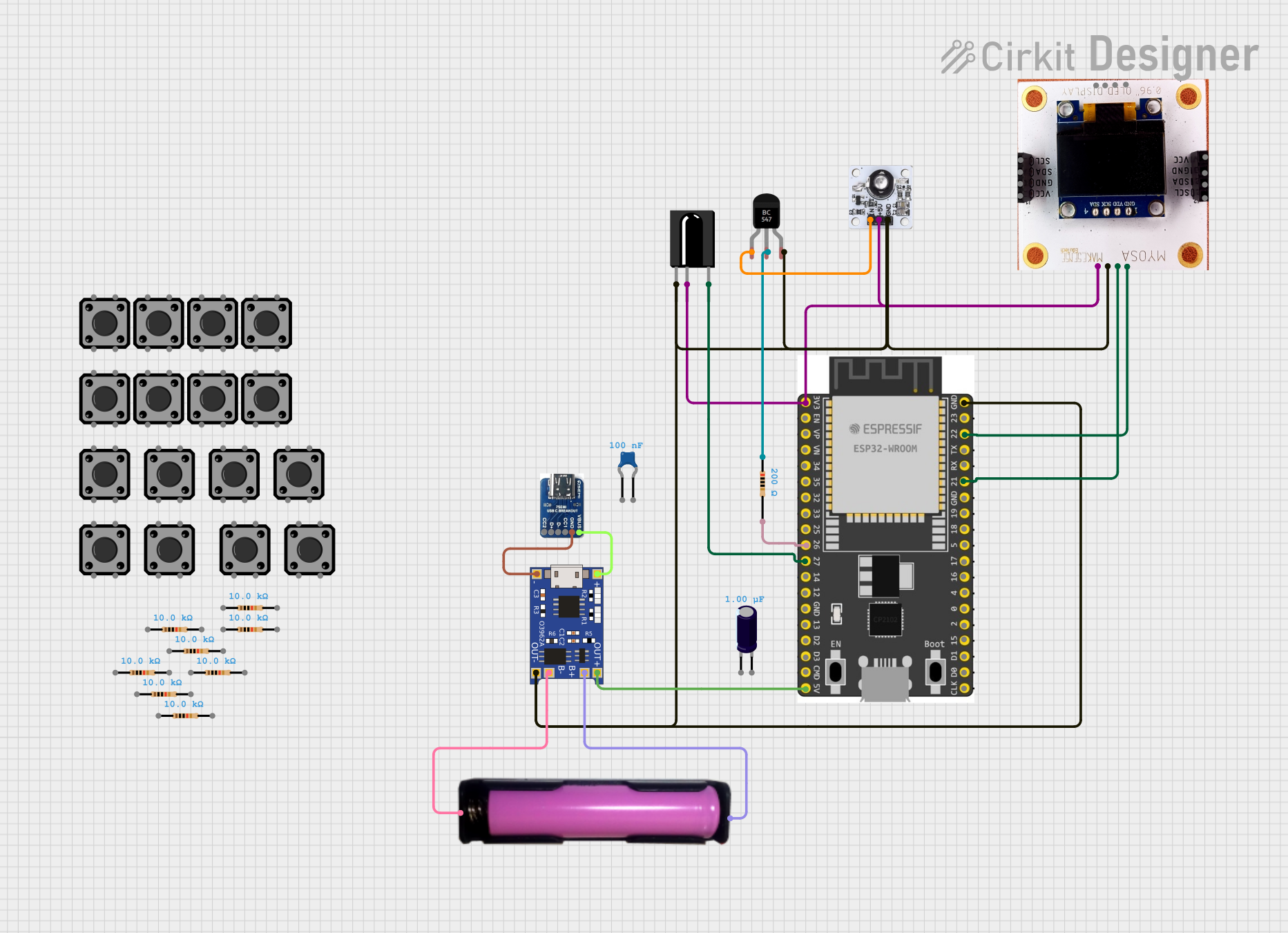 Open Project in Cirkit Designer
Explore Projects Built with Adafruit Infrared IR Remote Receiver
Open Project in Cirkit DesignerOpen Project in Cirkit DesignerOpen Project in Cirkit DesignerOpen Project in Cirkit DesignerCommon Applications and Use Cases
- Remote control of electronic devices (e.g., TVs, fans, lights)
- Wireless communication in robotics
- Home automation systems
- IR-based data transmission
- Learning and decoding IR signals for custom applications
Technical Specifications
The Adafruit Infrared IR Remote Receiver is designed for ease of use and compatibility with a wide range of microcontrollers, including Arduino boards. Below are the key technical details:
Key Technical Details
- Operating Voltage: 2.7V to 5.5V
- Current Consumption: ~0.4mA
- Carrier Frequency: 38kHz (optimized for most IR remote controls)
- Reception Distance: Up to 10 meters (depending on the remote and environment)
- Output Signal: Digital (active low)
- Operating Temperature: -25°C to +85°C
- Dimensions: 7.8mm x 5.3mm x 4.0mm (excluding pins)
Pin Configuration and Descriptions
The IR receiver has three pins, which are typically labeled on the component. Below is the pinout:
| Pin | Name | Description |
|---|---|---|
| 1 | VCC | Power supply pin. Connect to 3.3V or 5V depending on your microcontroller. |
| 2 | GND | Ground pin. Connect to the ground of your circuit. |
| 3 | OUT | Digital output pin. Outputs the decoded IR signal as a digital pulse stream. |
Usage Instructions
The Adafruit Infrared IR Remote Receiver is straightforward to use in a circuit. Follow the steps below to integrate it into your project:
Connecting the IR Receiver
- Power the Receiver: Connect the VCC pin to a 3.3V or 5V power source, depending on your microcontroller's logic level.
- Ground Connection: Connect the GND pin to the ground of your circuit.
- Signal Output: Connect the OUT pin to a digital input pin on your microcontroller (e.g., Arduino UNO pin 2).
Important Considerations and Best Practices
- Ensure the IR receiver is aligned with the IR transmitter (remote control) for optimal signal reception.
- Avoid placing the receiver in direct sunlight or near strong light sources, as this can interfere with IR signal detection.
- Use a pull-up resistor (10kΩ) on the OUT pin if the signal appears unstable.
- For best results, use a remote control operating at a 38kHz carrier frequency.
Example: Using with Arduino UNO
Below is an example of how to use the IR receiver with an Arduino UNO to decode IR signals:
Required Components
- Adafruit Infrared IR Remote Receiver
- Arduino UNO
- IR remote control
- Jumper wires
Circuit Diagram
- Connect the IR receiver's VCC pin to the Arduino's 5V pin.
- Connect the GND pin to the Arduino's GND pin.
- Connect the OUT pin to Arduino digital pin 2.
Arduino Code Example
#include <IRremote.h> // Include the IRremote library

const int RECV_PIN = 2; // Define the pin connected to the IR receiver's OUT pin
IRrecv irrecv(RECV_PIN); // Create an IRrecv object
decode_results results;  // Create a variable to store decoded IR data

void setup() {
  Serial.begin(9600); // Initialize serial communication for debugging
  irrecv.enableIRIn(); // Start the IR receiver
  Serial.println("IR Receiver is ready to decode signals.");
}

void loop() {
  if (irrecv.decode(&results)) { // Check if a signal is received
    Serial.print("IR Code: ");
    Serial.println(results.value, HEX); // Print the received IR code in hexadecimal
    irrecv.resume(); // Prepare to receive the next signal
  }
}
Notes on the Code
- Install the IRremote library in the Arduino IDE before uploading the code.
- The received IR codes will be displayed in the Serial Monitor. Use these codes to identify button presses on your remote control.
Troubleshooting and FAQs
Common Issues and Solutions
No Signal Detected:
- Ensure the IR receiver is properly connected to the power supply and ground.
- Verify that the remote control is functioning and emitting IR signals (use a smartphone camera to check for IR light).
- Check the alignment between the IR receiver and the remote control.
Unstable or Incorrect Signals:
- Add a pull-up resistor (10kΩ) to the OUT pin.
- Reduce ambient light interference by shielding the receiver from strong light sources.
Short Reception Range:
- Ensure the remote control's batteries are not depleted.
- Verify that there are no obstructions between the remote and the receiver.
FAQs
Q: Can this IR receiver work with any remote control?
A: The receiver is optimized for 38kHz carrier frequency, which is used by most standard remote controls. However, it may not work with remotes operating at different frequencies.
Q: Can I use this receiver with a 3.3V microcontroller?
A: Yes, the receiver operates at 2.7V to 5.5V, making it compatible with both 3.3V and 5V logic levels.
Q: How do I decode custom remote control signals?
A: Use the provided Arduino example to capture and log the IR codes. These codes can then be used to program custom actions in your project.
Q: What is the maximum range of this IR receiver?
A: The receiver can detect signals up to 10 meters away, depending on the remote control's power and environmental conditions.
By following this documentation, you can effectively integrate the Adafruit Infrared IR Remote Receiver into your projects for wireless control and communication.