How to Use 21 PIN: Examples, Pinouts, and Specs
Introduction
The 21-pin connector is a versatile electronic component designed to facilitate the interfacing of various devices and modules in a circuit. It provides a reliable means of establishing electrical connections between components, ensuring efficient signal transmission and power delivery. This connector is commonly used in applications such as audio-visual equipment, microcontroller projects, industrial automation, and custom PCB designs.
Explore Projects Built with 21 PIN


Explore Projects Built with 21 PIN
Common Applications:
- Audio-visual systems (e.g., SCART connectors in older TVs)
- Microcontroller and development board interfacing
- Industrial control systems
- Custom PCB-to-PCB connections
- Robotics and IoT projects
Technical Specifications
The 21-pin connector is available in various configurations, but the following specifications are typical for standard models:
| Parameter | Value |
|---|---|
| Number of Pins | 21 |
| Pin Pitch | 2.54 mm (standard) |
| Voltage Rating | 30V DC |
| Current Rating | 1A per pin |
| Operating Temperature | -40°C to +85°C |
| Contact Resistance | ≤ 20 mΩ |
| Insulation Resistance | ≥ 1000 MΩ |
| Connector Type | Male/Female |
| Mounting Style | Through-hole or Surface Mount |
| Material | Plastic housing, gold-plated pins |
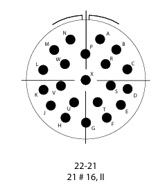
Pin Configuration and Descriptions
The pin configuration of a 21-pin connector can vary depending on the application. Below is a generic pinout for a 21-pin connector used in general-purpose interfacing:
| Pin Number | Description |
|---|---|
| 1 | Ground (GND) |
| 2 | Power Supply (VCC) |
| 3-8 | Data Lines (D0-D5) |
| 9-14 | Control Signals (C0-C5) |
| 15-20 | Auxiliary Signals (A0-A5) |
| 21 | Shield or Chassis Ground |
Note: Always refer to the specific datasheet or documentation for the exact pinout of your 21-pin connector, as it may vary depending on the manufacturer or intended use.
Usage Instructions
How to Use the 21-Pin Connector in a Circuit
- Identify the Pinout: Refer to the datasheet or pin configuration table to understand the function of each pin.
- Soldering: If using a through-hole connector, solder the pins to the PCB carefully to avoid short circuits. For surface-mount connectors, use a reflow soldering process.
- Cable Assembly: For cable connectors, crimp or solder the wires to the corresponding pins, ensuring proper insulation.
- Connection: Align the male and female connectors properly to avoid bending or damaging the pins.
- Testing: Verify the connections using a multimeter to ensure continuity and correct wiring.
Important Considerations and Best Practices
- Avoid Overloading: Do not exceed the voltage and current ratings of the connector to prevent damage.
- Proper Alignment: Ensure the connectors are properly aligned before mating to avoid pin damage.
- Environmental Protection: Use connectors with appropriate IP ratings if operating in harsh environments.
- Strain Relief: Use strain relief mechanisms to prevent stress on the wires or solder joints.
- Cleaning: Keep the connector contacts clean to maintain good electrical conductivity.
Example: Connecting a 21-Pin Connector to an Arduino UNO
Below is an example of how to use a 21-pin connector to interface an Arduino UNO with external components:
// Example: Reading data from a 21-pin connector using Arduino UNO
// Pin 3-8 (D0-D5) are connected to Arduino digital pins 2-7
// Pin 1 (GND) is connected to Arduino GND
// Pin 2 (VCC) is connected to Arduino 5V

void setup() {
  // Initialize pins 2-7 as inputs
  for (int pin = 2; pin <= 7; pin++) {
    pinMode(pin, INPUT);
  }
  Serial.begin(9600); // Start serial communication
}

void loop() {
  // Read data from pins 2-7 and print to Serial Monitor
  Serial.print("Data: ");
  for (int pin = 2; pin <= 7; pin++) {
    int value = digitalRead(pin);
    Serial.print(value);
    Serial.print(" ");
  }
  Serial.println(); // New line
  delay(500); // Wait for 500ms
}
Note: Ensure the external components connected to the 21-pin connector are compatible with the Arduino's voltage levels.
Troubleshooting and FAQs
Common Issues
Loose Connections:
- Cause: Improper mating of male and female connectors.
- Solution: Ensure the connectors are fully seated and aligned.
Signal Interference:
- Cause: Crosstalk between adjacent pins.
- Solution: Use shielded cables or connectors with better isolation.
Damaged Pins:
- Cause: Misalignment or excessive force during connection.
- Solution: Replace the damaged connector and handle with care.
No Signal Transmission:
- Cause: Incorrect wiring or broken solder joints.
- Solution: Verify the wiring and re-solder any broken connections.
FAQs
Q1: Can I use the 21-pin connector for high-speed data transmission?
A1: Yes, but ensure the connector is designed for high-speed applications and use shielded cables to minimize interference.
Q2: How do I prevent corrosion on the pins?
A2: Use connectors with gold-plated pins and store them in a dry environment.
Q3: Can I use the 21-pin connector for power delivery?
A3: Yes, but ensure the current does not exceed the 1A per pin rating. For higher currents, use multiple pins in parallel.
Q4: Are all 21-pin connectors standardized?
A4: No, the pinout and specifications may vary depending on the manufacturer and application. Always refer to the specific datasheet.
By following this documentation, you can effectively use the 21-pin connector in your projects while avoiding common pitfalls.