How to Use Engine with gearbox 6VDC 200rpm side: Examples, Pinouts, and Specs
Introduction
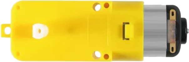
The Engine with Gearbox 6VDC 200RPM Side is a compact and efficient DC motor equipped with a built-in gearbox. The gearbox reduces the motor's speed to 200 revolutions per minute (RPM), significantly increasing torque output. This makes it ideal for applications requiring precise, low-speed, high-torque motion. The motor operates at 6V DC, making it compatible with a wide range of power sources, including batteries and microcontroller-based systems.
Explore Projects Built with Engine with gearbox 6VDC 200rpm side

Explore Projects Built with Engine with gearbox 6VDC 200rpm side
Common Applications and Use Cases
- Robotics: Driving wheels, arms, or other mechanical components.
- Conveyor belts: Providing controlled motion for small-scale systems.
- Automated systems: Used in vending machines, door openers, and other mechanisms.
- DIY projects: Ideal for hobbyists building motorized models or tools.
Technical Specifications
Below are the key technical details of the Engine with Gearbox 6VDC 200RPM Side:
| Parameter | Value |
|---|---|
| Operating Voltage | 6V DC |
| No-Load Speed | 200 RPM |
| Gearbox Ratio | 1:30 |
| Stall Torque | ~2.5 kg·cm |
| No-Load Current | ~120 mA |
| Stall Current | ~1.2 A |
| Shaft Diameter | 6 mm |
| Motor Dimensions | 70 mm x 30 mm x 25 mm |
| Weight | ~100 g |
Pin Configuration and Descriptions
The motor has two terminals for electrical connections:
| Pin | Description |
|---|---|
| + | Positive terminal for 6V DC input |
| - | Negative terminal (ground) for 6V DC |
Usage Instructions
How to Use the Component in a Circuit
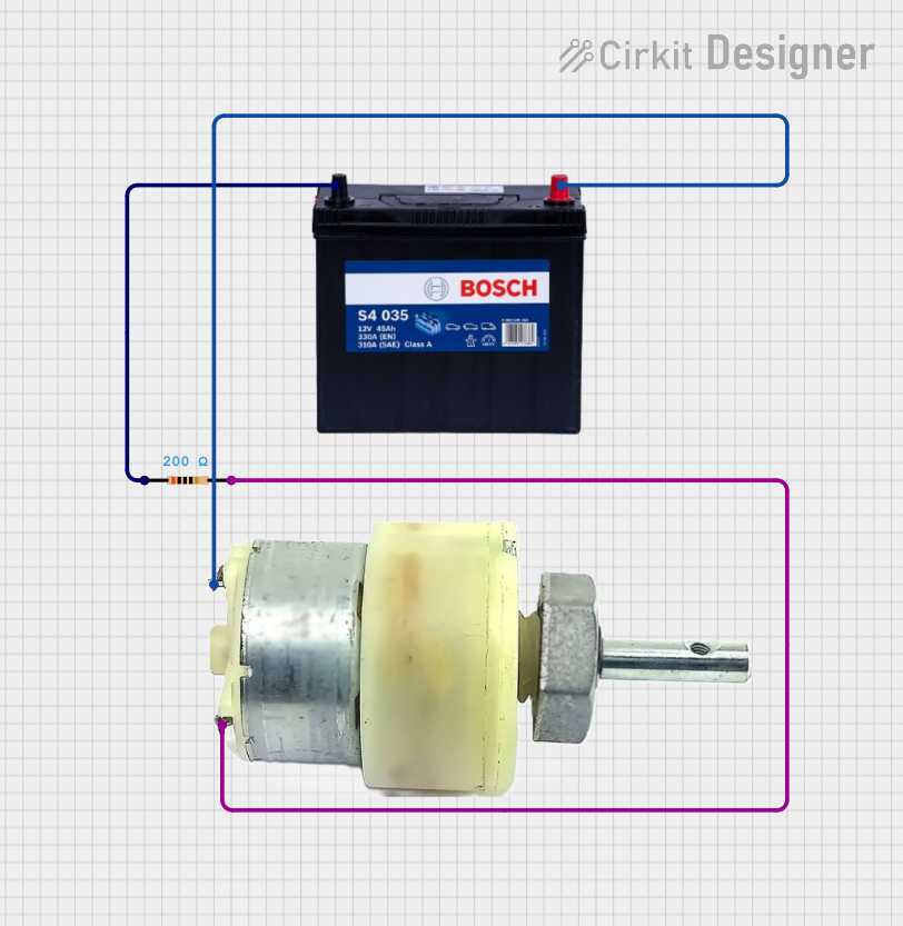
- Power Supply: Connect the motor's terminals to a 6V DC power source. Ensure the power supply can provide sufficient current (at least 1.2 A for stall conditions).
- Polarity Control: Reversing the polarity of the connections will reverse the motor's rotation direction.
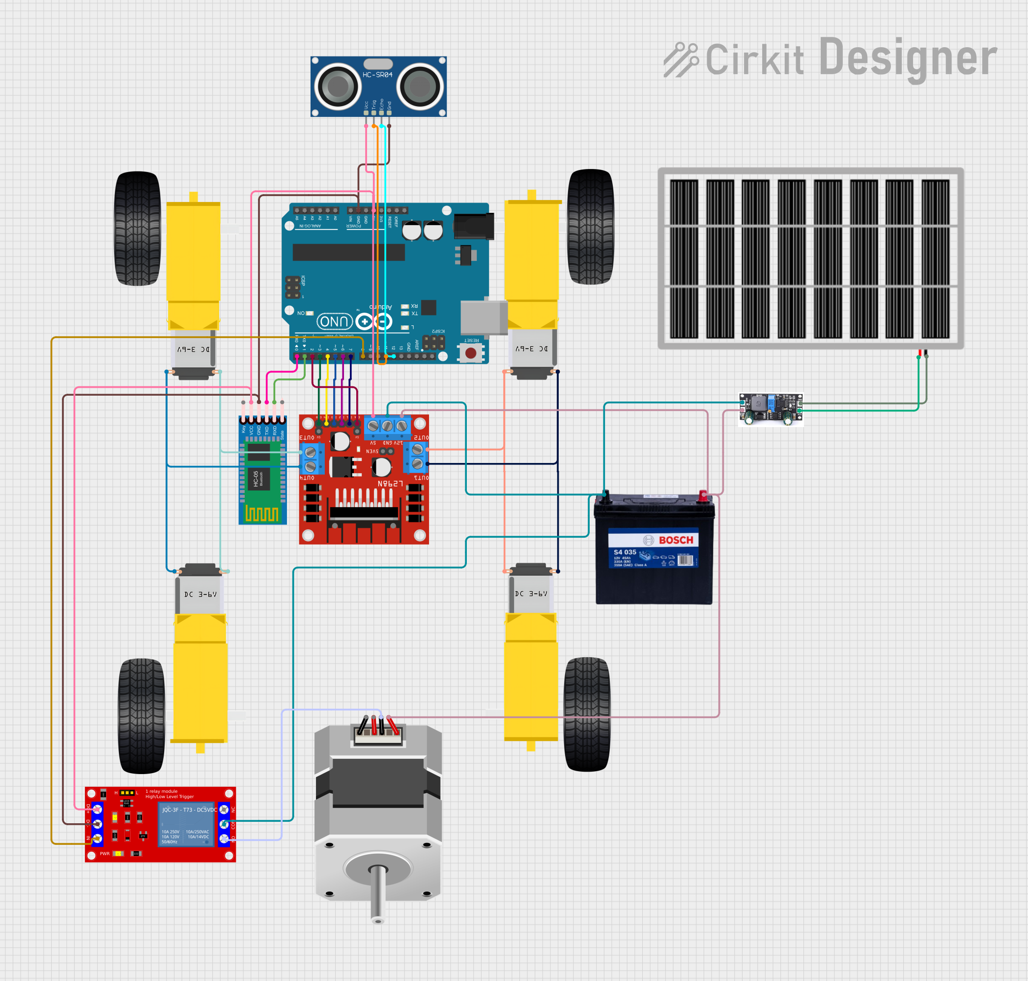
- Motor Driver: For microcontroller-based systems (e.g., Arduino), use an H-bridge motor driver (e.g., L298N or L293D) to control the motor's speed and direction.
- Mounting: Secure the motor using screws or brackets to prevent movement during operation.
Important Considerations and Best Practices
- Avoid Overloading: Do not exceed the motor's stall torque, as this can damage the gearbox or motor windings.
- Heat Management: Prolonged operation at high currents may cause the motor to overheat. Allow cooling periods if necessary.
- Power Supply: Use a regulated power supply to avoid voltage spikes that could damage the motor.
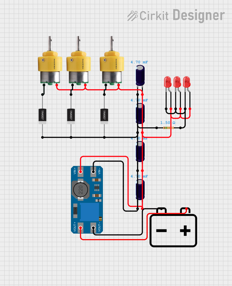
- Noise Suppression: Add a capacitor (e.g., 0.1 µF) across the motor terminals to reduce electrical noise.
Example: Connecting to an Arduino UNO
Below is an example of how to control the motor using an Arduino UNO and an L298N motor driver:
// Example: Controlling a 6V DC motor with Arduino and L298N motor driver

// Define motor control pins
const int motorPin1 = 9; // IN1 on L298N
const int motorPin2 = 10; // IN2 on L298N
const int enablePin = 11; // ENA on L298N (PWM control)

void setup() {
  // Set motor control pins as outputs
  pinMode(motorPin1, OUTPUT);
  pinMode(motorPin2, OUTPUT);
  pinMode(enablePin, OUTPUT);
}

void loop() {
  // Rotate motor forward
  digitalWrite(motorPin1, HIGH); // Set IN1 high
  digitalWrite(motorPin2, LOW);  // Set IN2 low
  analogWrite(enablePin, 128);   // Set speed (0-255, 128 = ~50% speed)
  delay(2000);                   // Run for 2 seconds

  // Stop motor
  analogWrite(enablePin, 0);     // Set speed to 0
  delay(1000);                   // Wait for 1 second

  // Rotate motor backward
  digitalWrite(motorPin1, LOW);  // Set IN1 low
  digitalWrite(motorPin2, HIGH); // Set IN2 high
  analogWrite(enablePin, 128);   // Set speed (0-255, 128 = ~50% speed)
  delay(2000);                   // Run for 2 seconds

  // Stop motor
  analogWrite(enablePin, 0);     // Set speed to 0
  delay(1000);                   // Wait for 1 second
}
Troubleshooting and FAQs
Common Issues and Solutions
Motor Does Not Spin:
- Cause: Insufficient power supply or loose connections.
- Solution: Check the power source and ensure all connections are secure.
Motor Spins in the Wrong Direction:
- Cause: Polarity of the connections is reversed.
- Solution: Swap the + and - connections to reverse the direction.
Motor Overheats:
- Cause: Prolonged operation at high current or excessive load.
- Solution: Reduce the load or allow the motor to cool periodically.
Excessive Noise or Vibration:
- Cause: Loose mounting or worn-out gearbox.
- Solution: Secure the motor properly and inspect the gearbox for damage.
FAQs
Can I use a higher voltage than 6V?
- No, exceeding 6V may damage the motor or gearbox.
What is the maximum weight the motor can handle?
- The motor can handle loads up to ~2.5 kg·cm of torque. Ensure the load does not exceed this limit.
Can I control the speed without a motor driver?
- Yes, by using a variable resistor or PWM circuit, but a motor driver is recommended for precise control.
Is the motor waterproof?
- No, the motor is not waterproof. Avoid exposing it to water or moisture.