How to Use MKS SERVO42D: Examples, Pinouts, and Specs
Introduction
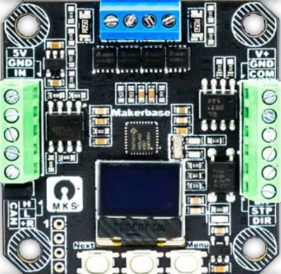
The MKS SERVO42D is a high-performance digital servo motor developed by Makerbase, designed for precise control in robotics, CNC machines, and other automation applications. With its robust metal gear train, high torque output, and fast response time, the MKS SERVO42D is ideal for tasks requiring accurate positioning and reliable operation. This servo is equipped with advanced features such as closed-loop control and CAN communication, making it a versatile choice for modern projects.
Explore Projects Built with MKS SERVO42D

Explore Projects Built with MKS SERVO42D
Common Applications
- Robotics (e.g., robotic arms, humanoid robots)
- CNC machines and 3D printers
- Automated machinery
- Precision positioning systems
- DIY electronics and hobbyist projects
Technical Specifications
Below are the key technical details of the MKS SERVO42D:
| Parameter | Value |
|---|---|
| Manufacturer | Makerbase |
| Part ID | MKS_SERVO42D_CAN |
| Operating Voltage | 12V to 24V DC |
| Maximum Torque | 1.5 Nm |
| Communication Interface | CAN (Controller Area Network) |
| Control Mode | Closed-loop control |
| Gear Type | Metal gear train |
| Position Accuracy | ±0.1° |
| Maximum Speed | 300 RPM |
| Operating Temperature | -10°C to 50°C |
| Dimensions | 42mm x 42mm x 60mm |
| Weight | 200g |
Pin Configuration and Descriptions
The MKS SERVO42D features a standard connector for power, communication, and control. Below is the pinout description:
| Pin | Name | Description |
|---|---|---|
| 1 | V+ | Power supply input (12V to 24V DC) |
| 2 | GND | Ground connection |
| 3 | CAN_H | CAN bus high signal |
| 4 | CAN_L | CAN bus low signal |
| 5 | EN | Enable pin (active high) |
| 6 | DIR | Direction control pin |
| 7 | STEP | Step signal input for position control |
| 8 | NC | Not connected |
Usage Instructions
How to Use the MKS SERVO42D in a Circuit
- Power Supply: Connect the V+ and GND pins to a DC power supply within the range of 12V to 24V. Ensure the power supply can provide sufficient current for the servo's operation.
- Communication: Use the CAN_H and CAN_L pins to connect the servo to a CAN bus network. Ensure proper termination resistors are used on the CAN bus.
- Control Signals:
- Use the STEP and DIR pins for step/direction control.
- The EN pin can be used to enable or disable the servo.
- Mounting: Secure the servo to your project using the provided mounting holes. Ensure the servo is aligned properly to avoid mechanical stress.
Important Considerations
- Power Requirements: Ensure the power supply voltage is within the specified range (12V to 24V). Using a voltage outside this range may damage the servo.
- Heat Dissipation: The servo may generate heat during operation. Ensure proper ventilation or use a heatsink if necessary.
- CAN Communication: Configure the CAN bus baud rate and IDs correctly to avoid communication conflicts.
- Mechanical Load: Avoid exceeding the maximum torque rating (1.5 Nm) to prevent damage to the gear train.
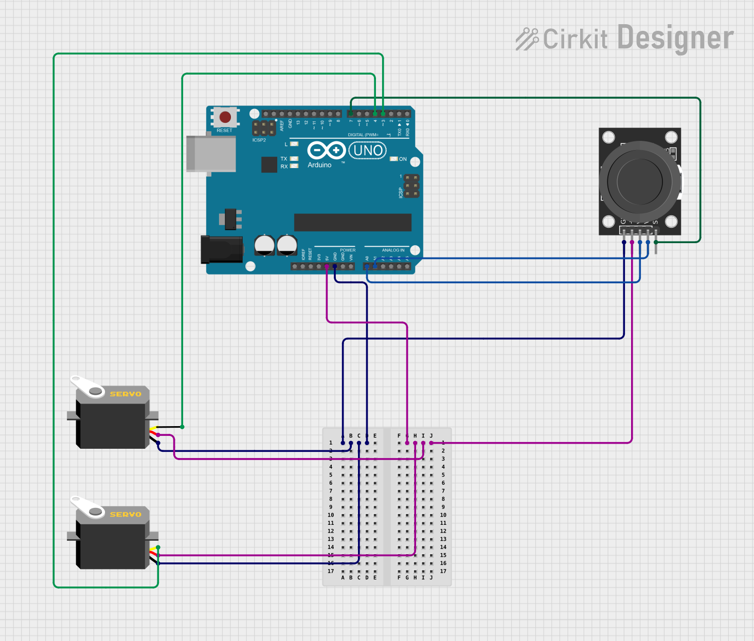
Example: Connecting to an Arduino UNO
The MKS SERVO42D can be controlled using an Arduino UNO via the STEP and DIR pins. Below is an example code snippet for basic control:
// Define pin connections
#define STEP_PIN 3  // Connect to the STEP pin of the servo
#define DIR_PIN 4   // Connect to the DIR pin of the servo
#define EN_PIN 5    // Connect to the EN pin of the servo

void setup() {
  // Set pin modes
  pinMode(STEP_PIN, OUTPUT);
  pinMode(DIR_PIN, OUTPUT);
  pinMode(EN_PIN, OUTPUT);

  // Enable the servo
  digitalWrite(EN_PIN, HIGH);
}

void loop() {
  // Set direction to clockwise
  digitalWrite(DIR_PIN, HIGH);

  // Generate step pulses
  for (int i = 0; i < 200; i++) { // 200 steps for one revolution
    digitalWrite(STEP_PIN, HIGH);
    delayMicroseconds(500); // Adjust for speed
    digitalWrite(STEP_PIN, LOW);
    delayMicroseconds(500);
  }

  delay(1000); // Wait for 1 second

  // Set direction to counterclockwise
  digitalWrite(DIR_PIN, LOW);

  // Generate step pulses
  for (int i = 0; i < 200; i++) {
    digitalWrite(STEP_PIN, HIGH);
    delayMicroseconds(500);
    digitalWrite(STEP_PIN, LOW);
    delayMicroseconds(500);
  }

  delay(1000); // Wait for 1 second
}
Notes:
- Adjust the
delayMicroseconds()value to control the speed of the servo. - Ensure the EN pin is set to HIGH to enable the servo.
Troubleshooting and FAQs
Common Issues and Solutions
Servo Not Responding
- Cause: Incorrect wiring or insufficient power supply.
- Solution: Double-check all connections and ensure the power supply meets the voltage and current requirements.
Erratic Movement
- Cause: Noise or interference on the control signals.
- Solution: Use shielded cables for signal lines and ensure proper grounding.
Overheating
- Cause: Excessive load or poor ventilation.
- Solution: Reduce the mechanical load and ensure adequate airflow around the servo.
CAN Communication Failure
- Cause: Incorrect baud rate or ID configuration.
- Solution: Verify the CAN bus settings and ensure proper termination resistors are in place.
FAQs
Q: Can the MKS SERVO42D be used with a 5V microcontroller?
A: Yes, but you may need a level shifter to interface the 5V logic with the servo's control pins.Q: What is the maximum cable length for the CAN bus?
A: The maximum length depends on the baud rate. For example, at 1 Mbps, the maximum length is approximately 40 meters.Q: Can I use the servo without a CAN bus?
A: Yes, the servo can be controlled using the STEP and DIR pins for basic operation.Q: Is the servo compatible with 3.3V logic?
A: Yes, the control pins are compatible with 3.3V and 5V logic levels.
This concludes the documentation for the MKS SERVO42D. For further assistance, refer to the official Makerbase resources or contact their support team.