How to Use 7segment on: Examples, Pinouts, and Specs
Introduction
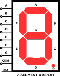
A 7-segment display is a form of electronic display device for displaying decimal numerals that is an alternative to the more complex dot matrix displays. 7-segment displays are widely used in digital clocks, electronic meters, basic calculators, and other electronic devices that display numerical information.
Explore Projects Built with 7segment on
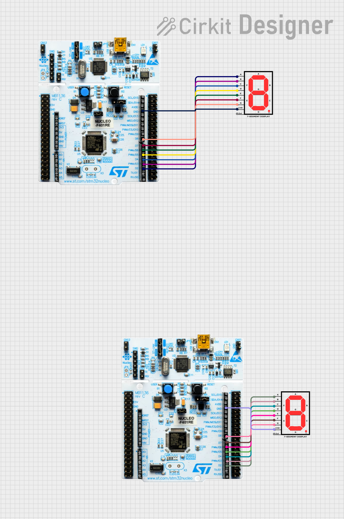
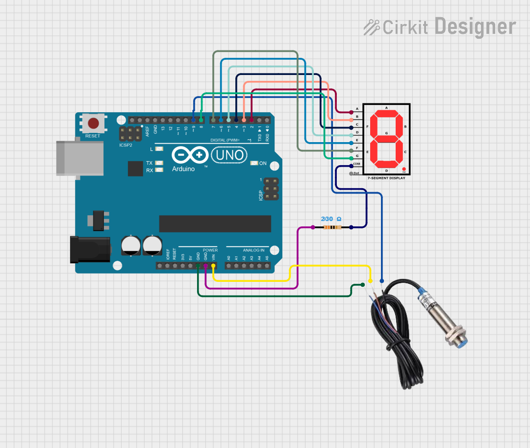
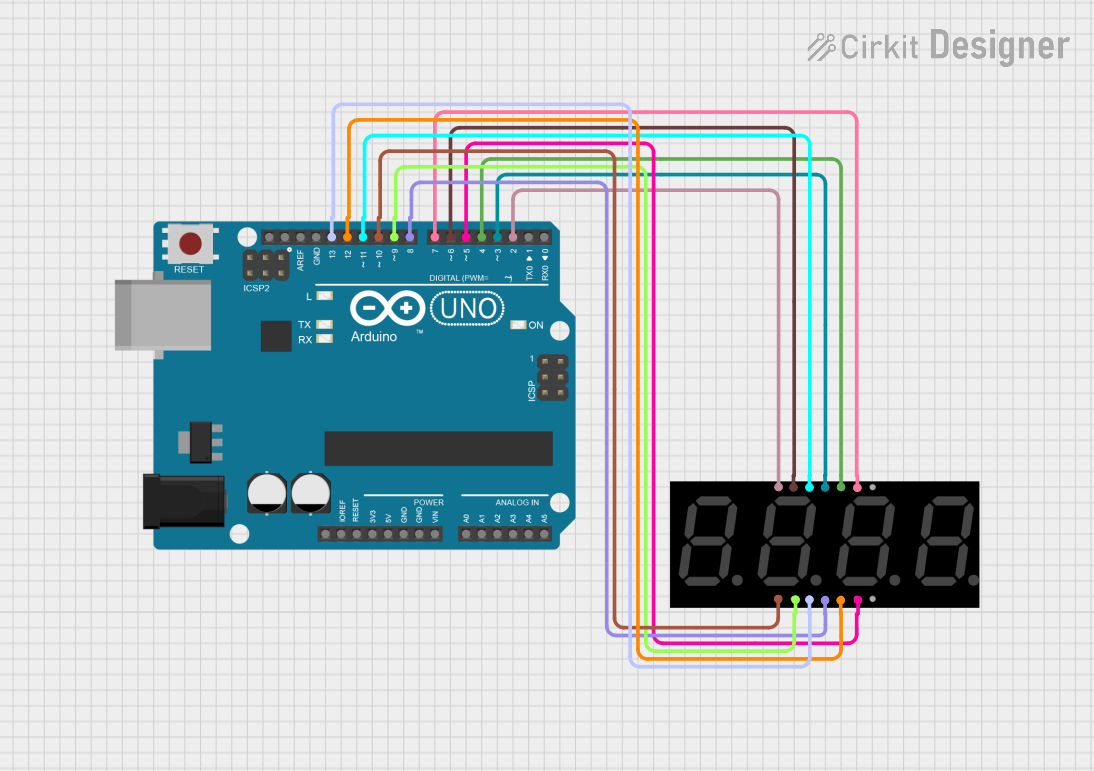
Explore Projects Built with 7segment on
Common Applications and Use Cases
- Digital clocks and timers
- Electronic meters (like voltmeters, ammeters)
- Calculators
- Scoreboards
- Price display in retail
Technical Specifications
Key Technical Details
- Operating Voltage: Typically 3.3V to 5V
- Forward Current: 10-20 mA per segment
- Luminous Intensity: Dependent on color and size, typically measured in mcd (millicandela)
Pin Configuration and Descriptions
| Pin No. | Function | Description |
|---|---|---|
| 1 | Segment E | Controls the E segment of the display |
| 2 | Segment D | Controls the D segment of the display |
| 3 | Common Anode/Cathode | Common pin for all segments (model specific) |
| 4 | Segment C | Controls the C segment of the display |
| 5 | Segment DP | Controls the decimal point of the display |
| 6 | Segment B | Controls the B segment of the display |
| 7 | Segment A | Controls the A segment of the display |
| 8 | Segment G | Controls the G segment of the display |
| 9 | Segment F | Controls the F segment of the display |
Note: The pin configuration may vary depending on the manufacturer and whether the display is common anode or common cathode.
Usage Instructions
How to Use the Component in a Circuit
- Identify the Type: Determine if your 7-segment display is common anode or common cathode.
- Connect Common Pin: Connect the common pin to VCC (for common cathode) or GND (for common anode).
- Resistors: Connect a current-limiting resistor (220-330 ohms) in series with each segment pin to prevent damage.
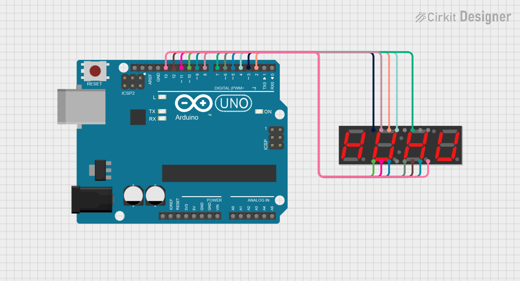
- Control Pins: Connect the segment pins to the digital output pins of a microcontroller, such as an Arduino UNO, to control the display.
Important Considerations and Best Practices
- Always use current-limiting resistors to prevent burning out the LEDs.
- Multiplexing can be used if you're controlling multiple displays to save on I/O pins.
- Ensure that the power supply can handle the current required for all segments if they are to be lit simultaneously.
Example Code for Arduino UNO
// Define the LED pin connections to Arduino
int segA = 2;
int segB = 3;
int segC = 4;
int segD = 5;
int segE = 6;
int segF = 7;
int segG = 8;
int segDP = 9;

// Define the digit to be displayed (0-9)
int digit = 5; // Example digit

void setup() {
  // Set all the segment pins as output
  pinMode(segA, OUTPUT);
  pinMode(segB, OUTPUT);
  pinMode(segC, OUTPUT);
  pinMode(segD, OUTPUT);
  pinMode(segE, OUTPUT);
  pinMode(segF, OUTPUT);
  pinMode(segG, OUTPUT);
  pinMode(segDP, OUTPUT);
}

void loop() {
  // Turn off all segments
  digitalWrite(segA, LOW);
  digitalWrite(segB, LOW);
  digitalWrite(segC, LOW);
  digitalWrite(segD, LOW);
  digitalWrite(segE, LOW);
  digitalWrite(segF, LOW);
  digitalWrite(segG, LOW);
  digitalWrite(segDP, LOW);

  // Display the chosen digit
  displayDigit(digit);
}

void displayDigit(int digit) {
  // Turn on the appropriate segments for the digit
  switch (digit) {
    case 0:
      digitalWrite(segA, HIGH);
      digitalWrite(segB, HIGH);
      digitalWrite(segC, HIGH);
      digitalWrite(segD, HIGH);
      digitalWrite(segE, HIGH);
      digitalWrite(segF, HIGH);
      break;
    // Add cases for digits 1-9
    // ...
    case 5:
      digitalWrite(segA, HIGH);
      digitalWrite(segF, HIGH);
      digitalWrite(segG, HIGH);
      digitalWrite(segC, HIGH);
      digitalWrite(segD, HIGH);
      break;
    // ...
    default:
      // Handle invalid digit
      break;
  }
}
Note: The above code assumes a common cathode 7-segment display. For a common anode display, you would reverse the HIGH and LOW states.
Troubleshooting and FAQs
Common Issues
- Segments not lighting up: Check the connections and ensure that the current-limiting resistors are in place.
- Dim segments: Ensure that the power supply is adequate and that the resistors are not too high in value.
- Incorrect display: Verify that the pin connections match the code and that the correct type of display (common anode/cathode) is being used.
Solutions and Tips for Troubleshooting
- Double-check wiring against the pin configuration.
- Use a multimeter to verify that each segment is receiving the correct voltage.
- Ensure that the microcontroller's output pins are functioning correctly by testing them with a simple LED circuit.
FAQs
Q: Can I use a 9V battery to power the 7-segment display? A: While a 9V battery can be used, you must ensure that the current-limiting resistors are calculated to drop the voltage to the appropriate level for the display.
Q: How can I display numbers larger than 9? A: To display numbers larger than 9, you will need to use multiple 7-segment displays and possibly implement multiplexing to control them with a limited number of microcontroller pins.
Q: Can I control a 7-segment display with a Raspberry Pi? A: Yes, you can control a 7-segment display with a Raspberry Pi, but you need to consider the voltage and current limitations of the Pi's GPIO pins and use appropriate interfacing components.