
How to Use MAGJACK: Examples, Pinouts, and Specs
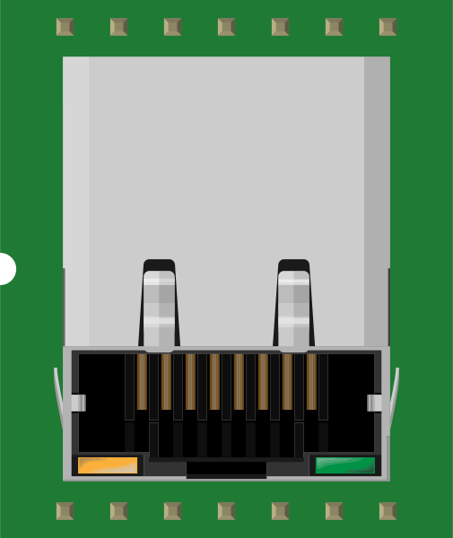
 Design with MAGJACK in Cirkit Designer
Introduction
MAGJACK is a modular connector system specifically designed for Ethernet applications. It provides a compact, reliable interface for network connections and is widely used in networking devices such as routers, switches, and embedded systems. One of its key features is the integration of magnetics, which ensures signal integrity and reduces electromagnetic interference (EMI). This makes MAGJACK an essential component for high-speed and stable Ethernet communication.
Explore Projects Built with MAGJACK
 Open Project in Cirkit Designer
 Open Project in Cirkit Designer
 Open Project in Cirkit Designer
 Open Project in Cirkit Designer
Explore Projects Built with MAGJACK
Open Project in Cirkit DesignerOpen Project in Cirkit DesignerOpen Project in Cirkit DesignerOpen Project in Cirkit DesignerCommon Applications and Use Cases
- Ethernet-enabled devices (e.g., routers, switches, IoT devices)
- Embedded systems requiring network connectivity
- Industrial automation and control systems
- Consumer electronics with Ethernet ports
- Power over Ethernet (PoE) applications
Technical Specifications
Key Technical Details
- Connector Type: RJ45 with integrated magnetics
- Ethernet Standards Supported: 10/100 Mbps, 1 Gbps (varies by model)
- Voltage Rating: 1.5 kV isolation (typical)
- Current Rating: 1.5 A per pin (typical)
- Operating Temperature: -40°C to +85°C
- Insertion Loss: ≤ 1.0 dB (typical at 100 MHz)
- Return Loss: ≥ 16 dB (typical at 100 MHz)
- Compliance: IEEE 802.3 Ethernet standards, RoHS compliant
Pin Configuration and Descriptions
Below is a typical pinout for a MAGJACK connector used in Ethernet applications. Note that the exact pin configuration may vary depending on the specific model.
| Pin Number | Signal Name | Description |
|---|---|---|
| 1 | TX+ | Transmit Data Positive |
| 2 | TX- | Transmit Data Negative |
| 3 | RX+ | Receive Data Positive |
| 4 | PoE V+ (optional) | Power over Ethernet Positive Voltage (if used) |
| 5 | PoE V+ (optional) | Power over Ethernet Positive Voltage (if used) |
| 6 | RX- | Receive Data Negative |
| 7 | PoE V- (optional) | Power over Ethernet Negative Voltage (if used) |
| 8 | PoE V- (optional) | Power over Ethernet Negative Voltage (if used) |
| Shield | Chassis Ground | Provides EMI shielding and grounding |
Usage Instructions
How to Use the MAGJACK in a Circuit
Placement on PCB:
- Place the MAGJACK connector near the Ethernet PHY (Physical Layer) chip to minimize signal loss.
- Ensure proper alignment with the PCB layout to match the pin configuration.
Power Supply:
- If using Power over Ethernet (PoE), ensure the power supply meets the IEEE 802.3af/at standards.
- Use appropriate decoupling capacitors to filter noise.
Signal Traces:
- Route differential pairs (TX+/TX-, RX+/RX-) with controlled impedance (typically 100 ohms).
- Keep the traces short and avoid sharp bends to maintain signal integrity.
Grounding and Shielding:
- Connect the shield pin to the chassis ground for EMI protection.
- Use a ground plane on the PCB to reduce noise and interference.
Testing:
- Verify the Ethernet link using a network analyzer or a connected device.
- Check for proper signal levels and minimal packet loss.
Important Considerations and Best Practices
- Magnetic Isolation: The integrated magnetics provide isolation between the Ethernet PHY and the external network. Ensure the isolation voltage rating meets your application requirements.
- PoE Compatibility: If using PoE, confirm that the MAGJACK model supports the required power levels.
- Thermal Management: For high-power applications, ensure adequate ventilation or heat dissipation around the connector.
- Compliance: Verify that the MAGJACK meets the required Ethernet standards (e.g., IEEE 802.3) for your application.
Example: Using MAGJACK with Arduino UNO
To connect an Arduino UNO to an Ethernet network, you can use an Ethernet shield that includes a MAGJACK connector. Below is an example code snippet to establish a basic Ethernet connection:
#include <SPI.h>
#include <Ethernet.h>

// MAC address and IP address for the Ethernet shield
byte mac[] = { 0xDE, 0xAD, 0xBE, 0xEF, 0xFE, 0xED };
IPAddress ip(192, 168, 1, 177);

// Initialize the Ethernet server on port 80
EthernetServer server(80);

void setup() {
  // Start the Ethernet connection
  Ethernet.begin(mac, ip);

  // Start the server
  server.begin();

  // Print the IP address to the serial monitor
  Serial.begin(9600);
  Serial.print("Server is at ");
  Serial.println(Ethernet.localIP());
}

void loop() {
  // Listen for incoming clients
  EthernetClient client = server.available();
  if (client) {
    Serial.println("New client connected");
    // Send a basic HTTP response
    client.println("HTTP/1.1 200 OK");
    client.println("Content-Type: text/html");
    client.println();
    client.println("<h1>Hello from MAGJACK Ethernet!</h1>");
    client.stop(); // Close the connection
  }
}
Troubleshooting and FAQs
Common Issues and Solutions
No Ethernet Link Detected:
- Cause: Incorrect wiring or damaged cable.
- Solution: Verify the connections and test with a known good Ethernet cable.
High Packet Loss:
- Cause: Poor PCB layout or long signal traces.
- Solution: Ensure proper routing of differential pairs with controlled impedance.
PoE Not Working:
- Cause: Incompatible MAGJACK model or insufficient power supply.
- Solution: Check the MAGJACK specifications and ensure the power supply meets the required standards.
Excessive EMI:
- Cause: Improper grounding or shielding.
- Solution: Connect the shield pin to the chassis ground and use a ground plane on the PCB.
FAQs
Q: Can I use MAGJACK for Gigabit Ethernet?
- A: Yes, but ensure the specific MAGJACK model supports 1 Gbps speeds.
Q: Is MAGJACK compatible with PoE+?
- A: Some models support PoE+ (IEEE 802.3at). Check the datasheet for compatibility.
Q: How do I test the isolation provided by the integrated magnetics?
- A: Use a high-voltage tester to verify the isolation rating (e.g., 1.5 kV).
Q: Can I use MAGJACK in outdoor applications?
- A: Yes, but ensure the connector is housed in a weatherproof enclosure to protect it from environmental factors.