How to Use Adafruit PCM5102 I2S DAC: Examples, Pinouts, and Specs
Introduction
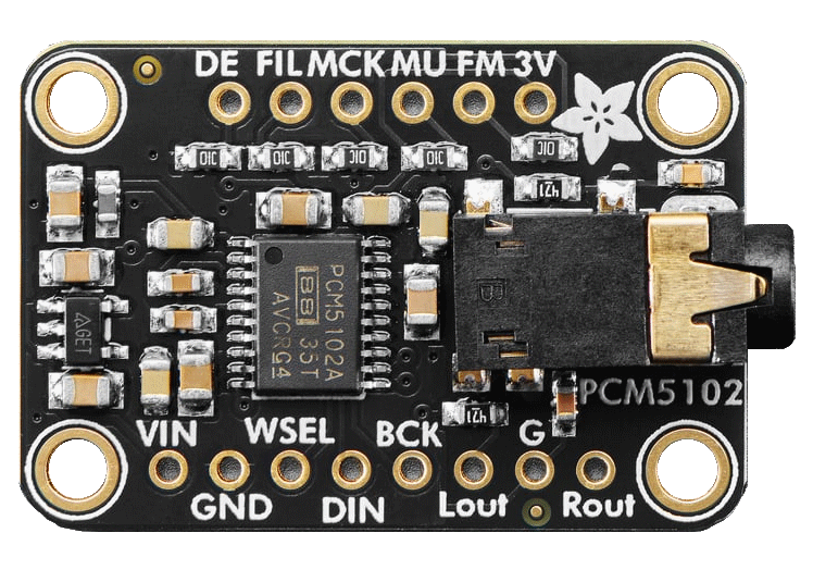
The Adafruit PCM5102 I2S DAC (Manufacturer Part ID: 1528-6250-ND) is a high-quality digital-to-analog converter (DAC) designed to convert I2S audio data into analog audio signals. This component is ideal for applications requiring excellent sound quality, such as audio playback systems, DIY audio projects, and embedded systems with audio output capabilities. Its compact design and ease of use make it a popular choice for hobbyists and professionals alike.
Explore Projects Built with Adafruit PCM5102 I2S DAC
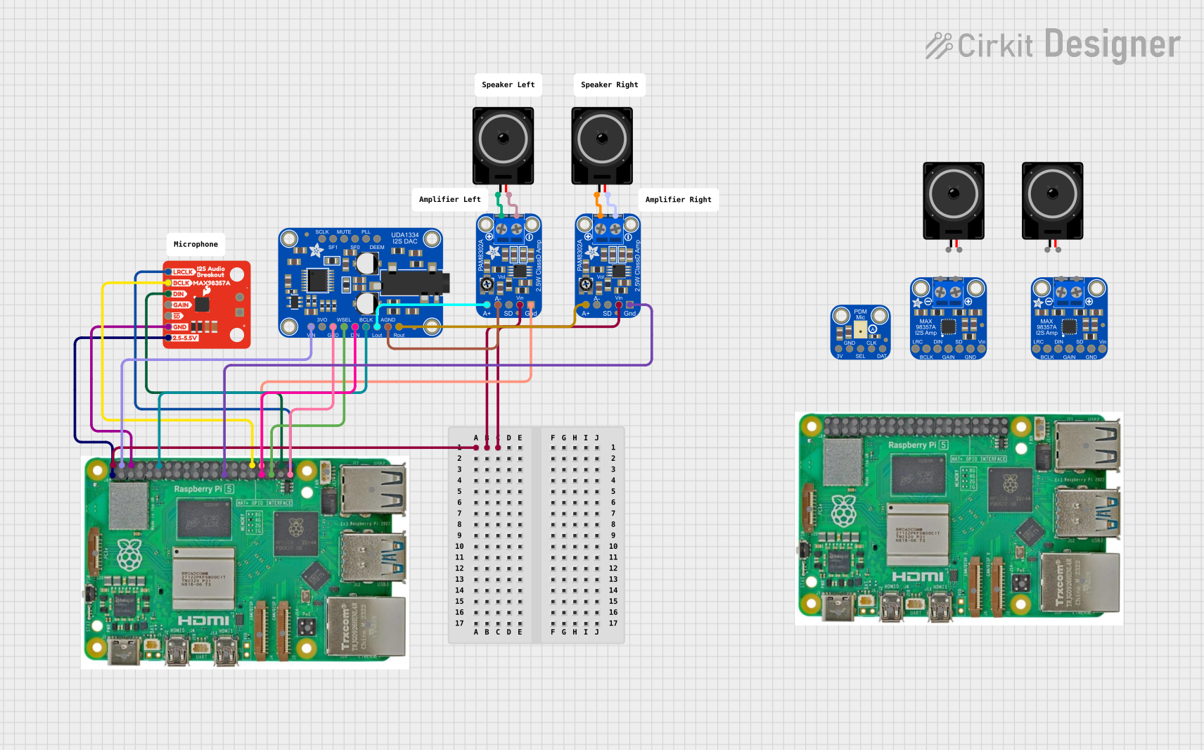
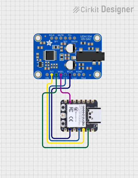
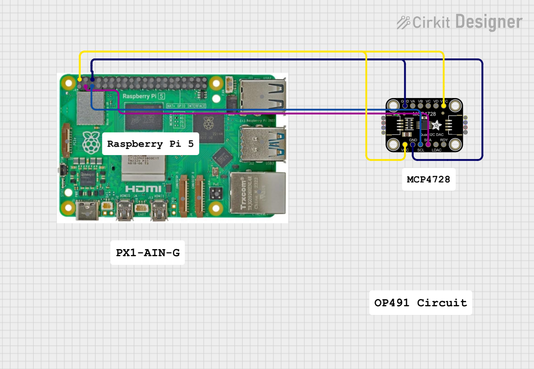

Explore Projects Built with Adafruit PCM5102 I2S DAC
Common Applications and Use Cases
- High-fidelity audio playback systems
- DIY audio amplifiers and speakers
- Embedded systems with audio output
- Raspberry Pi and Arduino-based audio projects
- Digital music players and sound processing systems
Technical Specifications
The Adafruit PCM5102 I2S DAC is built to deliver high-quality audio performance with low noise and distortion. Below are its key technical specifications:
Key Technical Details
- Input Interface: I2S (Inter-IC Sound)
- Output: Stereo analog audio (Left and Right channels)
- Power Supply Voltage: 3.3V to 5V DC
- Sampling Rates: Supports up to 384 kHz
- Bit Depth: 16-bit, 24-bit, or 32-bit audio
- Signal-to-Noise Ratio (SNR): 112 dB
- Total Harmonic Distortion + Noise (THD+N): -93 dB
- Output Voltage: 2.1 Vrms (typical)
- Operating Temperature Range: -40°C to +85°C
- Dimensions: 25mm x 20mm x 3mm (approx.)
Pin Configuration and Descriptions
The PCM5102 I2S DAC module has the following pinout:
| Pin Name | Type | Description |
|---|---|---|
| VIN | Power Input | Power supply input (3.3V to 5V DC). |
| GND | Ground | Ground connection. |
| BCK | Input | Bit clock input for I2S data. |
| LCK | Input | Left-right clock (word select) input for I2S data. |
| DIN | Input | Data input for I2S audio stream. |
| FLT | Output | Filter select pin (leave unconnected for default operation). |
| XMT | Output | Mute control pin (active low, leave unconnected for default operation). |
| SCL | Input (Optional) | Serial clock input for advanced configuration (not typically used). |
| SDA | Input (Optional) | Serial data input for advanced configuration (not typically used). |
| LOUT | Output | Left channel analog audio output. |
| ROUT | Output | Right channel analog audio output. |
Usage Instructions
The Adafruit PCM5102 I2S DAC is straightforward to use in audio projects. Below are the steps and considerations for integrating it into your circuit.
How to Use the Component in a Circuit
- Power the Module: Connect the VIN pin to a 3.3V or 5V DC power source and the GND pin to ground.
- Connect I2S Signals:
- Connect the
BCKpin to the bit clock output of your microcontroller or audio source. - Connect the
LCKpin to the left-right clock (word select) output. - Connect the
DINpin to the data output of your microcontroller or audio source.
- Connect the
- Audio Output:
- Connect the
LOUTpin to the left channel of your audio amplifier or speaker. - Connect the
ROUTpin to the right channel of your audio amplifier or speaker.
- Connect the
- Optional Pins:
- Leave the
FLTandXMTpins unconnected for default operation. - The
SCLandSDApins are not required for basic operation and can be left unconnected.
- Leave the
Important Considerations and Best Practices
- Ensure that the I2S signals from your microcontroller or audio source are compatible with the PCM5102 module.
- Use decoupling capacitors near the power supply pins to reduce noise and improve stability.
- Avoid connecting the module to power sources exceeding 5V to prevent damage.
- For best audio quality, use shielded cables for the analog audio output and keep the module away from high-frequency noise sources.
Example: Connecting to an Arduino UNO
The PCM5102 I2S DAC can be connected to an Arduino UNO using an I2S interface. However, note that the Arduino UNO does not natively support I2S. You will need an external I2S-compatible microcontroller (e.g., ESP32) or an I2S shield for Arduino.
Below is an example of using the PCM5102 with an ESP32:
Wiring Diagram
| PCM5102 Pin | ESP32 Pin |
|---|---|
| VIN | 3.3V |
| GND | GND |
| BCK | GPIO26 |
| LCK | GPIO25 |
| DIN | GPIO22 |
| LOUT | Left channel of amplifier/speaker |
| ROUT | Right channel of amplifier/speaker |
Example Code
#include "driver/i2s.h"

// I2S configuration for ESP32
#define I2S_NUM         I2S_NUM_0  // Use I2S port 0
#define I2S_BCK_IO      26         // Bit clock pin
#define I2S_LRCK_IO     25         // Left-right clock pin
#define I2S_DATA_IO     22         // Data output pin

void setup() {
  // Configure I2S
  i2s_config_t i2s_config = {
    .mode = (i2s_mode_t)(I2S_MODE_MASTER | I2S_MODE_TX), // Master mode, TX only
    .sample_rate = 44100,                               // Sampling rate
    .bits_per_sample = I2S_BITS_PER_SAMPLE_16BIT,       // 16-bit audio
    .channel_format = I2S_CHANNEL_FMT_RIGHT_LEFT,       // Stereo format
    .communication_format = I2S_COMM_FORMAT_I2S,        // I2S standard
    .intr_alloc_flags = 0,                              // Default interrupt allocation
    .dma_buf_count = 8,                                 // Number of DMA buffers
    .dma_buf_len = 64                                   // Size of each DMA buffer
  };

  // Configure I2S pins
  i2s_pin_config_t pin_config = {
    .bck_io_num = I2S_BCK_IO,
    .ws_io_num = I2S_LRCK_IO,
    .data_out_num = I2S_DATA_IO,
    .data_in_num = I2S_PIN_NO_CHANGE // Not used
  };

  // Install and start I2S driver
  i2s_driver_install(I2S_NUM, &i2s_config, 0, NULL);
  i2s_set_pin(I2S_NUM, &pin_config);
}

void loop() {
  // Example: Send a simple sine wave to the DAC
  static const int amplitude = 1000;
  static const int frequency = 440; // 440 Hz (A4 note)
  static const int sample_rate = 44100;
  static int sample_index = 0;

  int16_t sample = amplitude * sin(2 * PI * frequency * sample_index / sample_rate);
  i2s_write(I2S_NUM, &sample, sizeof(sample), NULL, portMAX_DELAY);
  sample_index++;
}
Troubleshooting and FAQs
Common Issues and Solutions
No Audio Output:
- Verify that the I2S signals (BCK, LCK, and DIN) are correctly connected and active.
- Check the power supply voltage (3.3V to 5V) and ensure proper grounding.
- Ensure that the audio amplifier or speaker is correctly connected to the
LOUTandROUTpins.
Distorted Audio:
- Ensure that the sampling rate and bit depth of the I2S data match the PCM5102's capabilities.
- Use shielded cables for analog audio output to reduce noise.
Module Overheating:
- Check for excessive input voltage (above 5V) and ensure proper ventilation.
FAQs
Can I use the PCM5102 with a Raspberry Pi? Yes, the PCM5102 is compatible with the Raspberry Pi's I2S interface. You can connect it to the GPIO pins and configure the I2S interface in the Raspberry Pi's settings.
What is the maximum sampling rate supported? The PCM5102 supports sampling rates up to 384 kHz.
Do I need external components for basic operation? No, the PCM5102 module is ready to use out of the box. However, decoupling capacitors and an audio amplifier are recommended for optimal performance.