
How to Use Load Cell - Red/white/black/green: Examples, Pinouts, and Specs
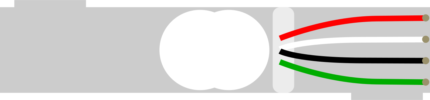
 Design with Load Cell - Red/white/black/green in Cirkit Designer
Introduction
A load cell is a transducer that converts a force or weight into an electrical signal. It is widely used in applications requiring precise weight or force measurement, such as digital scales, industrial weighing systems, and force measurement devices. The load cell with red, white, black, and green wires is a common configuration, where each wire serves a specific purpose for power, signal output, and ground connections.
This component is ideal for projects involving weight measurement, such as smart scales, robotics, and IoT-based monitoring systems.
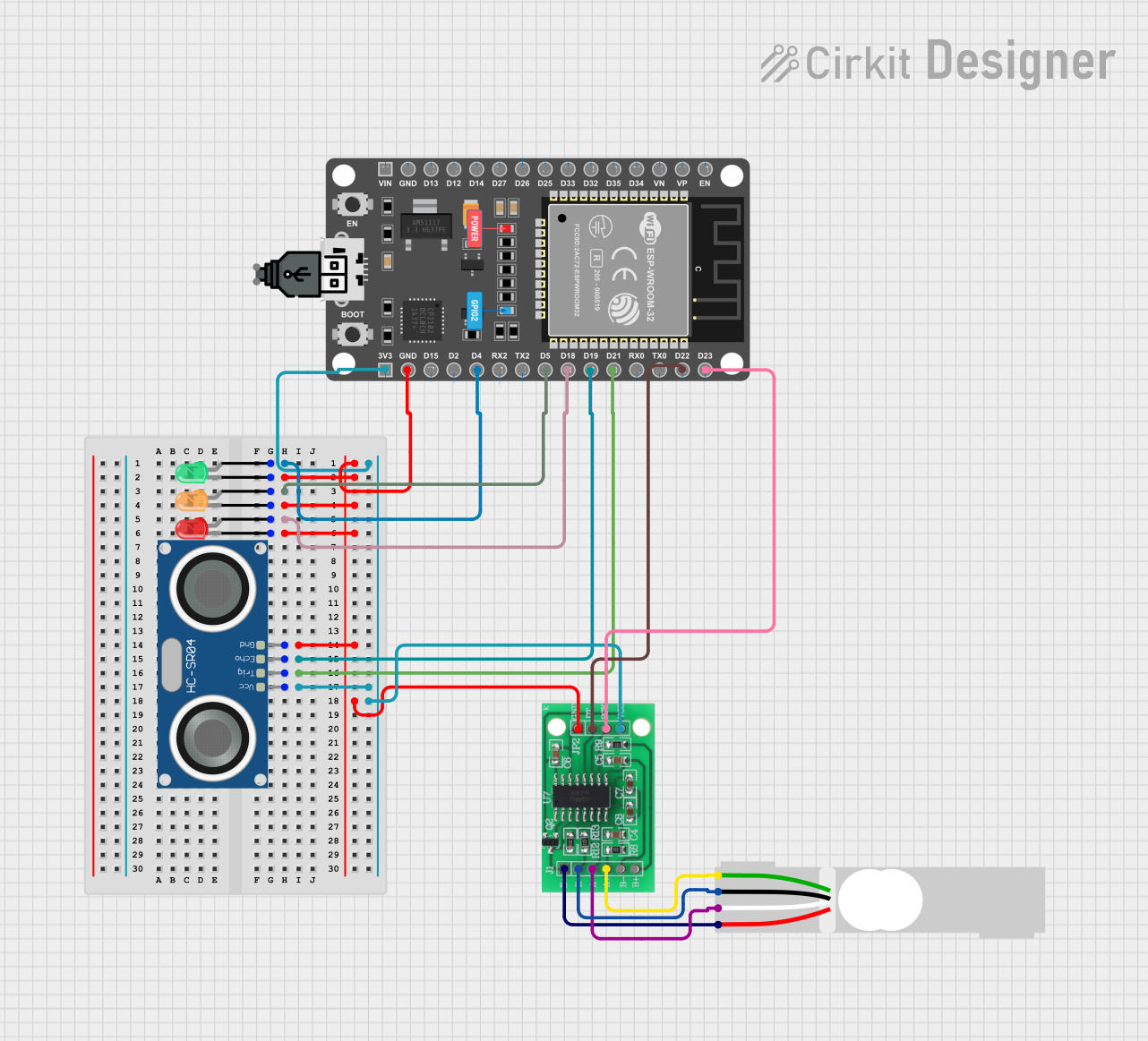
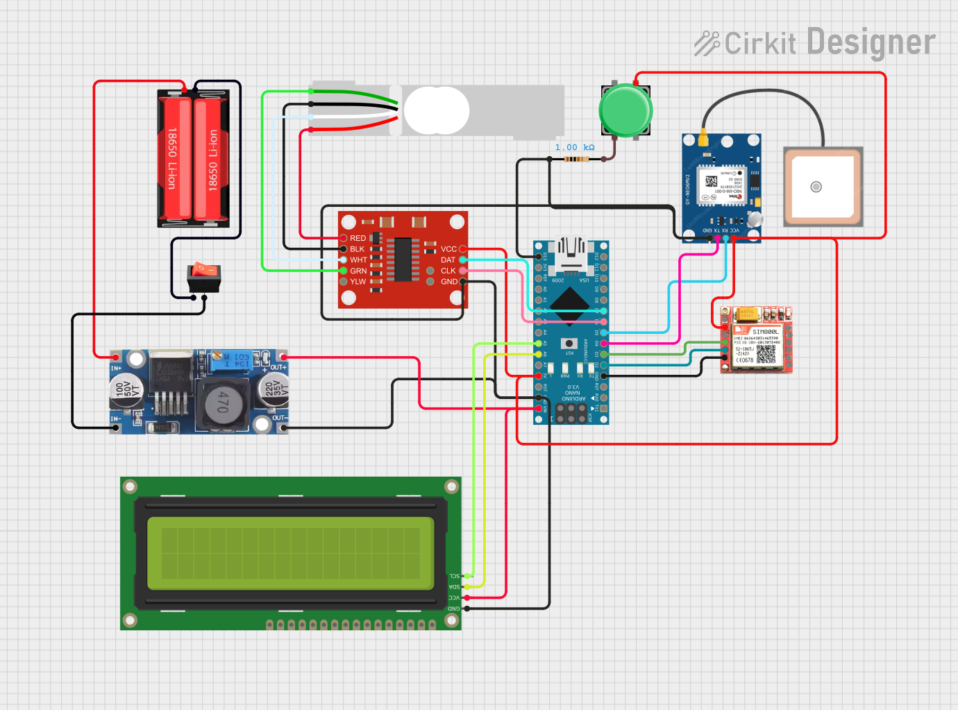
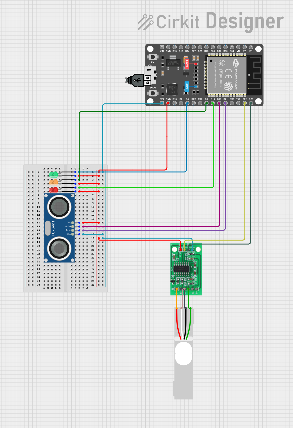
Explore Projects Built with Load Cell - Red/white/black/green
 Open Project in Cirkit Designer
 Open Project in Cirkit Designer
 Open Project in Cirkit Designer
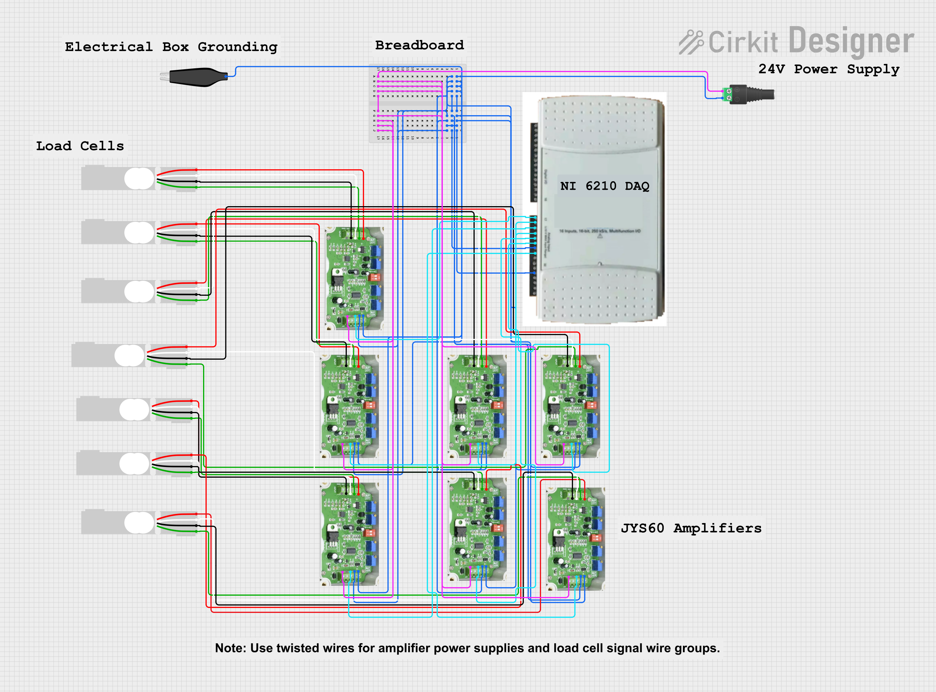 Open Project in Cirkit Designer
Explore Projects Built with Load Cell - Red/white/black/green
Open Project in Cirkit DesignerOpen Project in Cirkit DesignerOpen Project in Cirkit DesignerOpen Project in Cirkit DesignerTechnical Specifications
- Type: Strain gauge-based load cell
- Rated Load: Typically 1kg, 5kg, 10kg, or higher (varies by model)
- Excitation Voltage: 5V DC (recommended), up to 12V DC (maximum)
- Output Signal: Millivolt range (e.g., 1-3mV/V)
- Accuracy: ±0.02% of full scale (varies by model)
- Wiring Configuration: 4-wire (Red, White, Black, Green)
- Material: Aluminum alloy or stainless steel (varies by model)
- Operating Temperature: -10°C to +40°C
Pin Configuration and Descriptions
The load cell has four wires, each with a specific function:
| Wire Color | Function | Description |
|---|---|---|
| Red | Excitation+ (VCC) | Positive power supply input (typically 5V DC). |
| Black | Excitation- (GND) | Ground connection for the power supply. |
| White | Signal+ (Output+) | Positive differential signal output. |
| Green | Signal- (Output-) | Negative differential signal output. |
Usage Instructions
How to Use the Load Cell in a Circuit
Connect the Load Cell to an Amplifier:
The output signal of a load cell is in the millivolt range and needs to be amplified. Use an HX711 load cell amplifier module for this purpose.Wiring the Load Cell to the HX711:
- Connect the load cell wires to the HX711 module as follows:
- Red wire to E+ (Excitation+)
- Black wire to E- (Excitation-)
- White wire to A+ (Signal+)
- Green wire to A- (Signal-)
- Connect the HX711 module to a microcontroller (e.g., Arduino UNO).
- Connect the load cell wires to the HX711 module as follows:
Power the Circuit:
- Provide 5V DC to the HX711 module and ensure a common ground with the microcontroller.
Calibrate the Load Cell:
- Use a known weight to calibrate the load cell and determine the scale factor.
Important Considerations and Best Practices
- Mounting: Ensure the load cell is securely mounted to avoid mechanical vibrations or misalignment.
- Overloading: Do not exceed the rated load capacity to prevent permanent damage.
- Temperature Effects: Use the load cell within its specified operating temperature range to maintain accuracy.
- Shielding: Use shielded cables to minimize noise interference in the signal.
Example Code for Arduino UNO
Below is an example code to interface the load cell with an Arduino UNO using the HX711 module:
#include "HX711.h"

// Define HX711 pins
#define DT 3  // Data pin connected to Arduino pin 3
#define SCK 2 // Clock pin connected to Arduino pin 2

HX711 scale;

void setup() {
  Serial.begin(9600); // Initialize serial communication
  scale.begin(DT, SCK); // Initialize HX711 with defined pins

  Serial.println("Calibrating... Place a known weight on the load cell.");
  delay(5000); // Wait for user to place a weight
  scale.set_scale(); // Set the scale factor to default
  scale.tare(); // Reset the scale to 0
  Serial.println("Calibration complete.");
}

void loop() {
  // Read weight from the load cell
  float weight = scale.get_units(); // Get weight in units (grams or kilograms)
  Serial.print("Weight: ");
  Serial.print(weight);
  Serial.println(" kg");

  delay(1000); // Wait 1 second before the next reading
}
Note: Replace scale.set_scale() with the actual scale factor obtained during calibration.
Troubleshooting and FAQs
Common Issues and Solutions
No Output Signal:
- Cause: Incorrect wiring or loose connections.
- Solution: Double-check the wiring between the load cell, HX711, and microcontroller.
Inconsistent Readings:
- Cause: Mechanical vibrations or unstable mounting.
- Solution: Ensure the load cell is securely mounted and free from external vibrations.
Output Signal Saturation:
- Cause: Overloading the load cell beyond its rated capacity.
- Solution: Use a load cell with a higher rated capacity.
Noise in Signal:
- Cause: Electromagnetic interference or unshielded cables.
- Solution: Use shielded cables and keep the load cell away from high-frequency noise sources.
FAQs
Q: Can I use a different amplifier instead of HX711?
A: Yes, but ensure the amplifier is compatible with strain gauge-based load cells and provides sufficient gain.Q: How do I calibrate the load cell?
A: Use a known weight and adjust the scale factor in your code until the output matches the actual weight.Q: Can I use the load cell with a 3.3V microcontroller?
A: Yes, but ensure the HX711 module is compatible with 3.3V logic levels.Q: What is the maximum cable length for the load cell?
A: Typically, up to 3 meters. For longer distances, use shielded cables to minimize signal loss and noise.
This documentation provides a comprehensive guide to using the load cell with red, white, black, and green wires. Follow the instructions and best practices to achieve accurate and reliable weight measurements in your projects.