How to Use PT4115: Examples, Pinouts, and Specs
Introduction
The PT4115, manufactured by UMW (Youtai Semiconductor Co., Ltd.), is a high-efficiency, constant-current LED driver designed for driving high-power LEDs. It operates with a wide input voltage range and features adjustable output current, thermal protection, and a simple external component configuration. The PT4115 is ideal for applications requiring efficient and reliable LED driving with minimal external components.
Explore Projects Built with PT4115


Explore Projects Built with PT4115
Common Applications
- LED lighting systems (e.g., residential, commercial, and industrial)
- Automotive LED lighting
- Flashlights and portable lighting devices
- Backlighting for LCD displays
- Architectural and decorative lighting
Technical Specifications
Key Technical Details
| Parameter | Value |
|---|---|
| Input Voltage Range | 6.5V to 30V |
| Output Current Range | Up to 1.2A (adjustable via external resistor) |
| Efficiency | Up to 97% |
| Switching Frequency | 100kHz to 1MHz |
| Dimming Control | PWM or Analog (linear dimming) |
| Thermal Shutdown | Yes |
| Package Type | SOT89-5 |
Pin Configuration and Descriptions
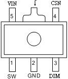
The PT4115B89E is available in the SOT89-5 package. The pinout and descriptions are as follows:
| Pin Number | Pin Name | Description |
|---|---|---|
| 1 | SW | Switch pin. Connect to the inductor and freewheeling diode. |
| 2 | GND | Ground pin. Connect to the system ground. |
| 3 | DIM | Dimming control pin. Accepts PWM or analog voltage for brightness control. |
| 4 | CSN | Current sense pin. Connect to a resistor to set the LED current. |
| 5 | VIN | Input voltage pin. Connect to the power supply. |
Usage Instructions
How to Use the PT4115 in a Circuit
- Power Supply: Connect a DC power supply (6.5V to 30V) to the VIN pin. Ensure the supply voltage matches the requirements of the LEDs being driven.
- Inductor and Diode: Connect an appropriate inductor and a Schottky diode to the SW pin. These components are critical for efficient operation.
- Current Setting Resistor: Use a resistor between the CSN pin and ground to set the desired LED current. The current can be calculated using the formula: [ I_{LED} = \frac{0.1}{R_{CS}} ] where ( R_{CS} ) is the resistance in ohms.
- Dimming Control: For dimming, apply a PWM signal (0-100% duty cycle) or an analog voltage (0.3V to 2.5V) to the DIM pin.
- LED Connection: Connect the LED(s) in series with the inductor and the SW pin. Ensure the total forward voltage of the LEDs is within the input voltage range.
Example Circuit
Below is a basic circuit diagram for using the PT4115 to drive a single high-power LED:
VIN (6.5V-30V) ----+----+----+----+----+----+----+----+
                   |    |    |    |    |    |    |    |
                  VIN   SW   DIM  CSN  GND  LED  L    D
Arduino Example for PWM Dimming
The PT4115 can be controlled using an Arduino UNO for PWM dimming. Connect the Arduino's PWM output pin to the DIM pin of the PT4115. Below is an example code snippet:
// PT4115 PWM Dimming Example
// Connect Arduino PWM pin (e.g., D9) to the DIM pin of the PT4115

const int dimPin = 9; // PWM pin connected to PT4115 DIM pin
int brightness = 0;   // Initial brightness level (0-255)
int fadeAmount = 5;   // Amount to change brightness by each step

void setup() {
  pinMode(dimPin, OUTPUT); // Set dimPin as an output
}

void loop() {
  analogWrite(dimPin, brightness); // Set brightness using PWM

  // Adjust brightness for fading effect
  brightness += fadeAmount;

  // Reverse direction of fading at limits
  if (brightness <= 0 || brightness >= 255) {
    fadeAmount = -fadeAmount;
  }

  delay(30); // Delay for smooth fading
}
Important Considerations
- Thermal Management: Ensure proper heat dissipation for the PT4115, especially when driving high currents. Use a PCB with adequate thermal vias and copper area.
- Inductor Selection: Choose an inductor with a suitable current rating and low DC resistance to minimize losses.
- Input Capacitor: Place a low-ESR capacitor close to the VIN pin to stabilize the input voltage.
- Output Capacitor: Use a capacitor at the LED output to reduce ripple and improve stability.
Troubleshooting and FAQs
Common Issues and Solutions
LEDs Not Lighting Up:
- Check the input voltage and ensure it is within the specified range (6.5V to 30V).
- Verify the connections and polarity of the LEDs.
- Ensure the current sense resistor is correctly calculated and connected.
Flickering LEDs:
- Check the stability of the input power supply.
- Verify the PWM signal on the DIM pin for proper operation.
- Ensure the inductor and capacitor values are appropriate for the circuit.
Overheating:
- Ensure proper thermal management with adequate PCB design.
- Reduce the LED current by increasing the value of the current sense resistor.
No Dimming Effect:
- Verify the PWM signal is being correctly generated by the microcontroller.
- Ensure the DIM pin voltage is within the specified range (0.3V to 2.5V for analog dimming).
FAQs
Q: Can the PT4115 drive multiple LEDs?
A: Yes, the PT4115 can drive multiple LEDs connected in series, provided the total forward voltage of the LEDs is less than the input voltage.
Q: What is the maximum current the PT4115 can handle?
A: The PT4115 can handle up to 1.2A of output current, depending on the value of the current sense resistor and thermal conditions.
Q: Can I use the PT4115 with a 5V power supply?
A: No, the minimum input voltage for the PT4115 is 6.5V. A higher voltage power supply is required.
Q: How do I calculate the inductor value?
A: The inductor value depends on the input voltage, output current, and switching frequency. Refer to the PT4115 datasheet for detailed calculations.
By following this documentation, users can effectively integrate the PT4115 into their LED driving applications with confidence.