
How to Use DC-DC 12V/24V to 5V 15A Converter 75W Step Down: Examples, Pinouts, and Specs
 Design with DC-DC 12V/24V to 5V 15A Converter 75W Step Down in Cirkit Designer
Introduction
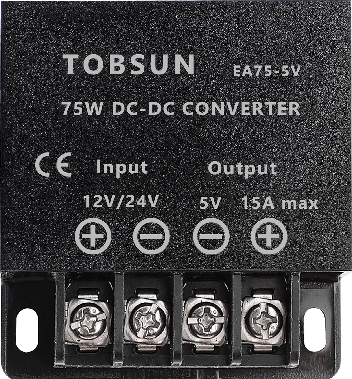
The Tobsun EA75-5V is a high-efficiency DC-DC step-down converter designed to convert input voltages of 12V or 24V to a stable 5V output. With a maximum output current of 15A and a power rating of 75W, this converter is ideal for powering a wide range of electronic devices, including microcontrollers, sensors, communication modules, and USB-powered devices. Its compact design and robust performance make it suitable for automotive, industrial, and hobbyist applications.
Explore Projects Built with DC-DC 12V/24V to 5V 15A Converter 75W Step Down
 Open Project in Cirkit Designer
 Open Project in Cirkit Designer
 Open Project in Cirkit Designer
 Open Project in Cirkit Designer
Explore Projects Built with DC-DC 12V/24V to 5V 15A Converter 75W Step Down
Open Project in Cirkit DesignerOpen Project in Cirkit DesignerOpen Project in Cirkit DesignerOpen Project in Cirkit DesignerCommon Applications
- Powering USB devices (e.g., smartphones, tablets, Raspberry Pi)
- Automotive electronics (e.g., dash cams, GPS units)
- Industrial control systems
- Battery-powered systems requiring a 5V rail
- DIY electronics and prototyping
Technical Specifications
Key Specifications
| Parameter | Value |
|---|---|
| Manufacturer | Tobsun |
| Part ID | EA75-5V |
| Input Voltage Range | 8V to 40V |
| Output Voltage | 5V (±2% regulation) |
| Maximum Output Current | 15A |
| Maximum Output Power | 75W |
| Efficiency | Up to 96% |
| Operating Temperature | -40°C to +85°C |
| Dimensions | 74mm x 74mm x 32mm |
| Weight | ~120g |
| Protection Features | Overcurrent, Overvoltage, |
| Overtemperature, Short Circuit |
Pin Configuration and Descriptions
The Tobsun EA75-5V converter has four connection terminals for input and output. The table below describes each terminal:
| Pin Label | Description |
|---|---|
| VIN+ | Positive input voltage (12V/24V) |
| VIN- | Negative input voltage (GND) |
| VOUT+ | Positive 5V output |
| VOUT- | Negative 5V output (GND) |
Usage Instructions
How to Use the Component in a Circuit
- Input Voltage Connection: Connect the VIN+ and VIN- terminals to a DC power source (e.g., a 12V car battery or a 24V industrial power supply). Ensure the input voltage is within the specified range (8V to 40V).
- Output Voltage Connection: Connect the VOUT+ and VOUT- terminals to the load requiring a 5V power supply. Ensure the load does not exceed the maximum output current of 15A.
- Secure Connections: Use appropriate wire gauges and connectors to handle the current requirements. Loose or undersized connections may cause overheating or voltage drops.
- Mounting: Secure the converter in a well-ventilated area to prevent overheating. Avoid placing it near heat-sensitive components.
- Testing: Before connecting sensitive devices, measure the output voltage with a multimeter to ensure it is stable at 5V.
Important Considerations and Best Practices
- Heat Dissipation: The converter may generate heat under high loads. Ensure adequate ventilation or use a heatsink if necessary.
- Input Voltage Range: Do not exceed the maximum input voltage of 40V, as this may damage the converter.
- Polarity: Double-check the polarity of the input and output connections to avoid damage.
- Load Requirements: Ensure the connected load does not exceed 15A. For higher loads, consider using multiple converters in parallel (if supported).
- Noise Filtering: If using the converter in sensitive applications, consider adding capacitors or filters to reduce electrical noise.
Example: Using with Arduino UNO
The Tobsun EA75-5V can be used to power an Arduino UNO and other peripherals. Below is an example wiring diagram and Arduino code to blink an LED:
Wiring Diagram
- Connect the VIN+ and VIN- terminals of the converter to a 12V DC power source.
- Connect the VOUT+ terminal to the Arduino UNO's 5V pin.
- Connect the VOUT- terminal to the Arduino UNO's GND pin.
- Connect an LED to pin 13 of the Arduino UNO with a 220-ohm resistor in series.
Arduino Code
// Simple LED Blink Example
// This code blinks an LED connected to pin 13 of the Arduino UNO.

void setup() {
  pinMode(13, OUTPUT); // Set pin 13 as an output
}

void loop() {
  digitalWrite(13, HIGH); // Turn the LED on
  delay(1000);            // Wait for 1 second
  digitalWrite(13, LOW);  // Turn the LED off
  delay(1000);            // Wait for 1 second
}
Troubleshooting and FAQs
Common Issues and Solutions
| Issue | Possible Cause | Solution |
|---|---|---|
| No output voltage | Incorrect input connections | Verify VIN+ and VIN- connections. |
| Input voltage out of range | Ensure input is between 8V and 40V. | |
| Output voltage fluctuates | Load exceeds maximum current rating | Reduce the load to ≤15A. |
| Insufficient input power | Use a higher-capacity power source. | |
| Converter overheats | Poor ventilation or high ambient temp | Improve airflow or add a heatsink. |
| Load near maximum power rating | Reduce the load or use multiple units. |
FAQs
Can I use this converter with a 6V input?
- No, the minimum input voltage is 8V. Using a lower voltage may result in unstable or no output.
Is the output voltage adjustable?
- No, the output voltage is fixed at 5V.
Can I connect multiple converters in parallel for higher current?
- It is not recommended unless the manufacturer explicitly supports parallel operation.
Does the converter have reverse polarity protection?
- No, reverse polarity may damage the converter. Always double-check connections.
Can I use this converter in outdoor environments?
- The converter is not waterproof. Use an appropriate enclosure for outdoor applications.