
How to Use Adafruit MOSFET Driver: Examples, Pinouts, and Specs
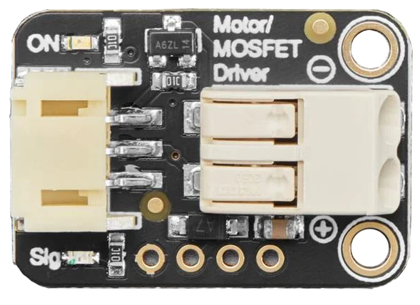
 Design with Adafruit MOSFET Driver in Cirkit Designer
Introduction
The Adafruit MOSFET Driver is a specialized circuit designed to control MOSFETs (Metal-Oxide-Semiconductor Field-Effect Transistors) efficiently. It enables high-speed switching and improved power management in electronic circuits. This driver is particularly useful in applications requiring precise control of high-power loads, such as motor drivers, LED lighting systems, and power converters. By providing the necessary gate drive voltage and current, the Adafruit MOSFET Driver ensures optimal MOSFET performance and minimizes switching losses.
Explore Projects Built with Adafruit MOSFET Driver
 Open Project in Cirkit Designer
 Open Project in Cirkit Designer
 Open Project in Cirkit Designer
 Open Project in Cirkit Designer
Explore Projects Built with Adafruit MOSFET Driver
Open Project in Cirkit DesignerOpen Project in Cirkit DesignerOpen Project in Cirkit DesignerOpen Project in Cirkit DesignerCommon Applications
- Motor control and speed regulation
- High-power LED lighting systems
- DC-DC converters and power supplies
- Pulse-width modulation (PWM) circuits
- Battery management systems
Technical Specifications
The Adafruit MOSFET Driver is designed to interface seamlessly with logic-level control signals, such as those from microcontrollers, while driving high-power MOSFETs. Below are the key technical details:
Key Specifications
| Parameter | Value |
|---|---|
| Input Voltage Range | 3.3V to 20V |
| Output Drive Voltage | Up to 20V (dependent on input) |
| Output Drive Current | 1.5A (peak) |
| Switching Frequency | Up to 1 MHz |
| Logic Input Voltage | 3.3V or 5V compatible |
| Operating Temperature | -40°C to +125°C |
| Package Type | DIP or SMD (varies by model) |
Pin Configuration
The Adafruit MOSFET Driver typically features a simple pinout for easy integration into circuits. Below is a standard pin configuration:
| Pin Number | Pin Name | Description |
|---|---|---|
| 1 | VCC | Power supply input (3.3V to 20V) |
| 2 | GND | Ground connection |
| 3 | IN | Logic-level input signal (PWM or digital) |
| 4 | OUT | Output to MOSFET gate |
Usage Instructions
How to Use the Adafruit MOSFET Driver
- Power Supply: Connect the VCC pin to a stable power source within the specified voltage range (3.3V to 20V). Connect the GND pin to the circuit ground.
- Logic Input: Connect the IN pin to a logic-level signal, such as a PWM output from a microcontroller (e.g., Arduino UNO). Ensure the input voltage matches the logic level of your microcontroller (3.3V or 5V).
- MOSFET Connection: Connect the OUT pin to the gate of the MOSFET you wish to control. Ensure the MOSFET's source and drain are connected appropriately for your application.
- Load Connection: Connect the load (e.g., motor, LED, etc.) to the MOSFET's drain and power supply as per your circuit design.
Important Considerations
- Gate Resistor: Use a small resistor (e.g., 10Ω) between the OUT pin and the MOSFET gate to limit inrush current and reduce ringing.
- Decoupling Capacitor: Place a decoupling capacitor (e.g., 0.1µF) close to the VCC and GND pins to stabilize the power supply.
- Heat Dissipation: Ensure proper heat dissipation for the MOSFET if driving high-power loads.
- Switching Frequency: Verify that the driver can handle the desired switching frequency without exceeding its maximum rating (1 MHz).
Example: Using with Arduino UNO
Below is an example of how to use the Adafruit MOSFET Driver with an Arduino UNO to control an LED strip using PWM.
Circuit Diagram
- Connect the VCC pin of the driver to a 12V power supply.
- Connect the GND pin to the Arduino GND.
- Connect the IN pin to Arduino pin 9 (PWM output).
- Connect the OUT pin to the gate of an N-channel MOSFET.
- Connect the LED strip to the MOSFET's drain and the 12V power supply.
Arduino Code
// Example code to control an LED strip using the Adafruit MOSFET Driver
// and Arduino UNO. The LED brightness is adjusted using PWM.

const int pwmPin = 9; // PWM pin connected to the IN pin of the MOSFET driver

void setup() {
  pinMode(pwmPin, OUTPUT); // Set the PWM pin as an output
}

void loop() {
  // Gradually increase brightness
  for (int brightness = 0; brightness <= 255; brightness++) {
    analogWrite(pwmPin, brightness); // Write PWM signal to the driver
    delay(10); // Small delay for smooth transition
  }

  // Gradually decrease brightness
  for (int brightness = 255; brightness >= 0; brightness--) {
    analogWrite(pwmPin, brightness); // Write PWM signal to the driver
    delay(10); // Small delay for smooth transition
  }
}
Troubleshooting and FAQs
Common Issues and Solutions
No Output Signal
- Cause: Incorrect power supply or loose connections.
- Solution: Verify that the VCC and GND pins are properly connected and the input voltage is within the specified range.
MOSFET Overheating
- Cause: Insufficient gate drive voltage or improper MOSFET selection.
- Solution: Ensure the driver provides adequate gate voltage for the MOSFET. Use a MOSFET with a low gate threshold voltage if necessary.
Erratic Switching
- Cause: Noise on the input signal or insufficient decoupling.
- Solution: Add a decoupling capacitor near the driver and ensure the input signal is clean.
Driver Overheating
- Cause: Excessive switching frequency or high output current.
- Solution: Reduce the switching frequency or ensure proper cooling for the driver.
FAQs
Q: Can I use the Adafruit MOSFET Driver with a 3.3V microcontroller?
A: Yes, the driver is compatible with both 3.3V and 5V logic levels.
Q: What type of MOSFETs can I use with this driver?
A: The driver is suitable for both N-channel and P-channel MOSFETs, but ensure the MOSFET's gate voltage requirements match the driver's output.
Q: Can I use this driver for high-frequency applications?
A: Yes, the driver supports switching frequencies up to 1 MHz, making it suitable for high-speed applications.
Q: Do I need a heatsink for the driver?
A: In most cases, a heatsink is not required. However, if operating at high frequencies or driving large loads, ensure proper heat dissipation.